This is the documentation of my final project for HCDE548 MAKING IT! We made it!
Ideation
We spent a few minutes ideating together what we wanted to make for final project in the class. It was a speed round and here are some of the ideas that’s always been in my head:
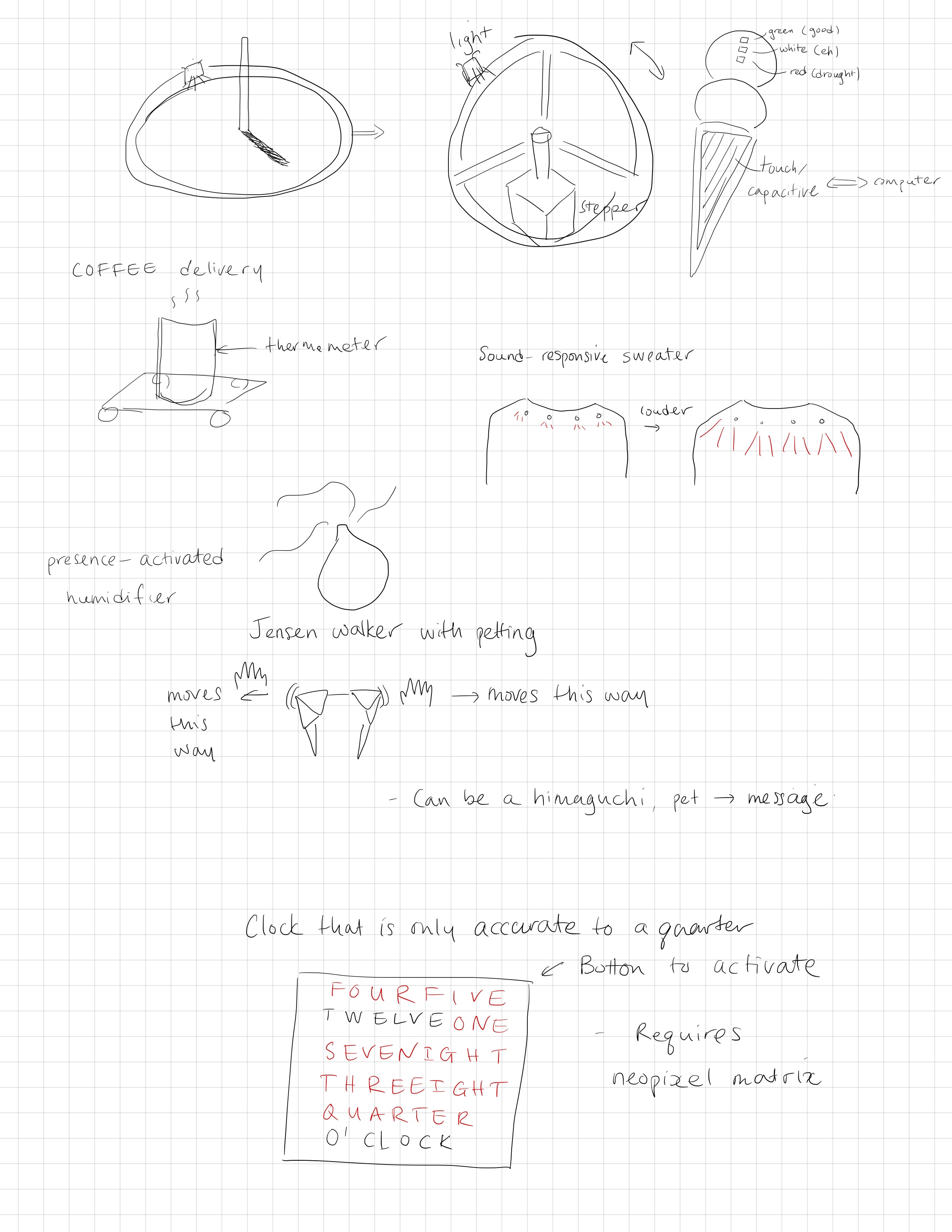
I decided to make the word clock. There are many copy cats these days but I believe this is the original and it is really expensive.
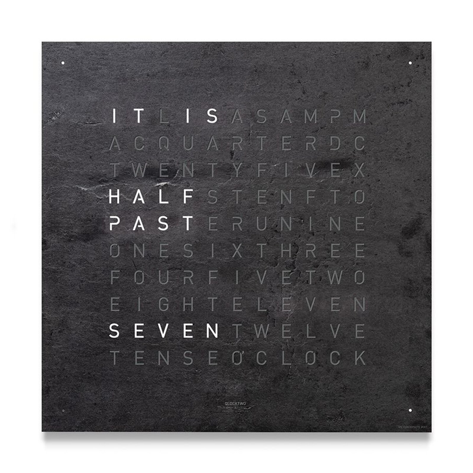
I always wanted one. I like the design and the expression of time in words. In Chinese, we have the same expression of ‘a quarter’ as 15 minutes. Our ancestor used water dripping to count time, much similar to a giant hourglass but with water in it. One day was divided into 100 segments and each ‘mark’, or ‘刻’, on the graduated container corresponds to 1/100 of a day, which is 14 minutes and 24 seconds. This translates to 15 minutes in modern timing system. I decided to make a clock that express time in quarters. I also like to use such expressions in my daily time-giving exercise.
Adafruit has this wonderful tutorial that basically just feeds the design to you. I hope my documentation will have the same effect for anyone who wants a Chinese no-so-accurate word clock.

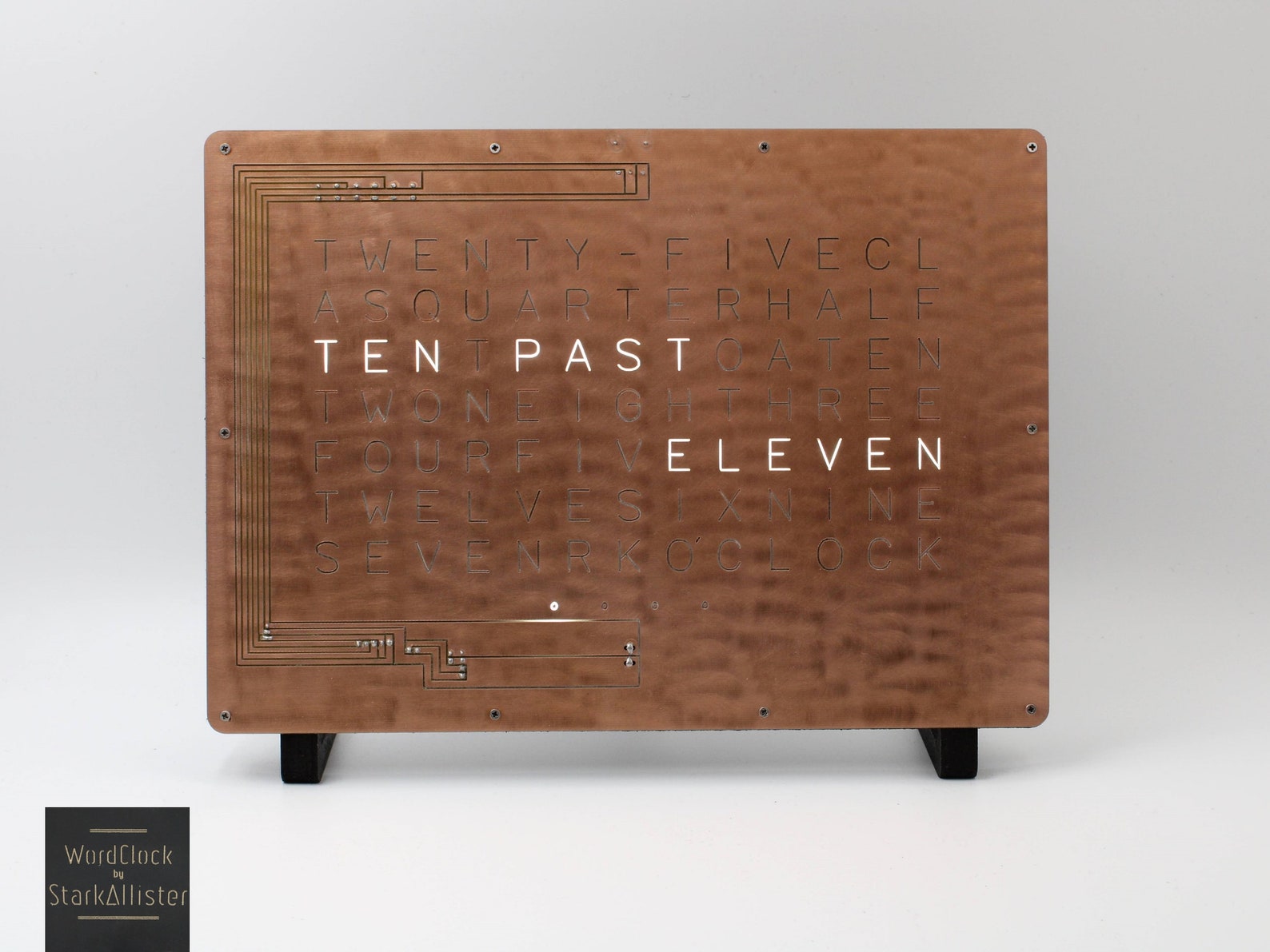
I also have to give a lot of credit of this Etsy shop owner StarkAllister who sells this word clock design in different languages. My design is inspired by it a lot.
Parts
We have been practicing making PCBs this whole time, so this post will also center around a (almost) start-from-scratch aspect of making it. There are still some electronic parts that I bought off-the-shelf. Overall, things you’ll need to replicate this project are:
Printed circuit board (Kicad file, schematics) fabricated by Bantam desktop milling tool
ATtiny44 as the microprocessor
DS1307 real time clock breakout
Adafruit NeoPixel strip, 60 LEDs per meter
(optional) Analog light sensor breakout
5V power cable
FTDI Serial TTL-232 USB Cable for serial communication (not necessary for the product but needed for debugging)
AVR-ISP mkII programmer or Arduino as programmer
Cardboard or foamboard as casing (I use foamboard as spacer between the clock face and the LED layer, and a backing that also holds the LEDs. The number of layers required depends on the thickness of the materials.)
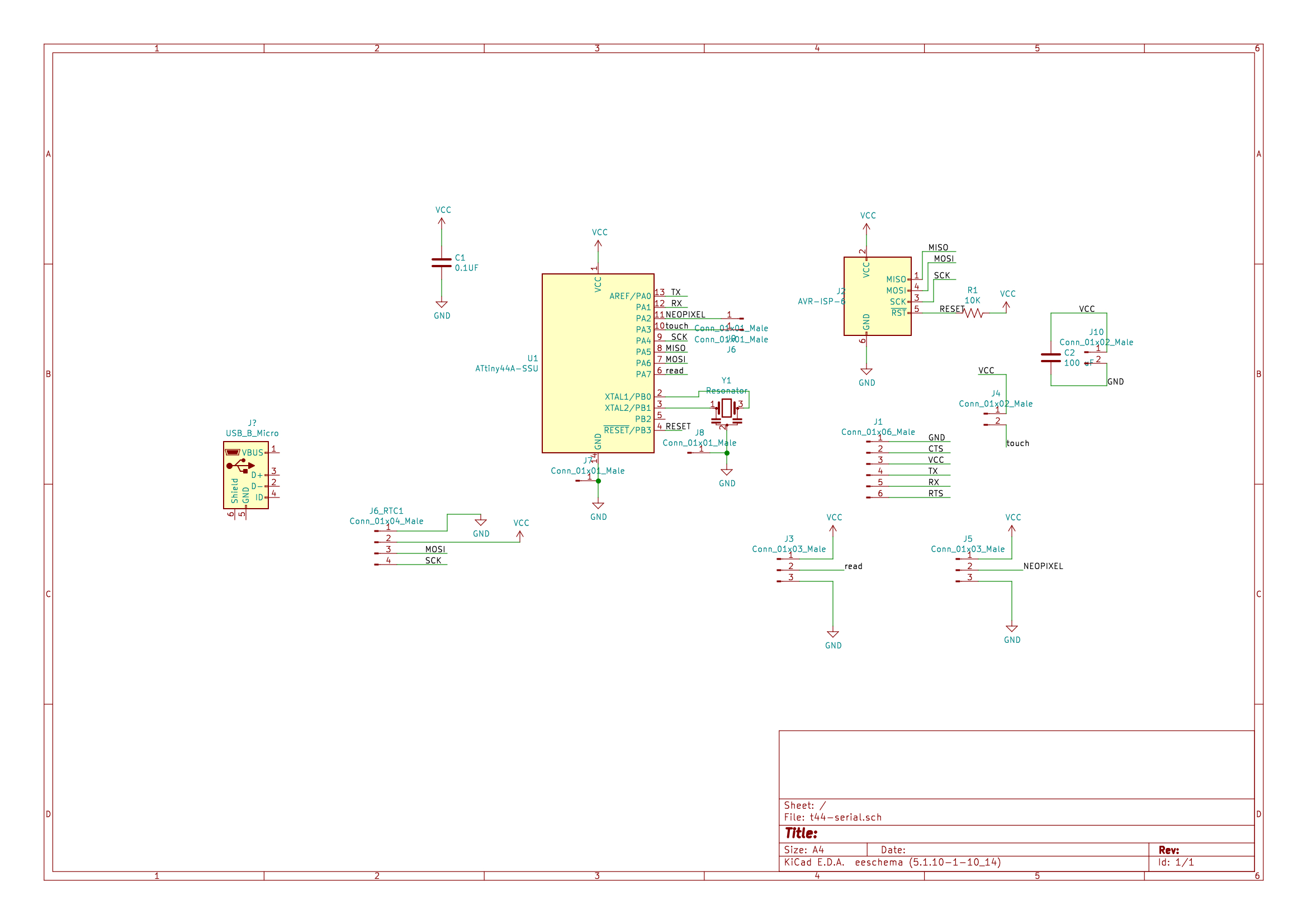
Board design
My board uses ATtiny44 as the microprocessor, has a 6-pin connectors for flashing the firmware, and a 6-pin serial communication port for reading sensor values and debugging.
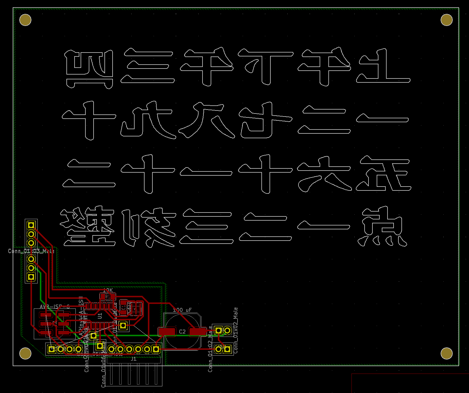
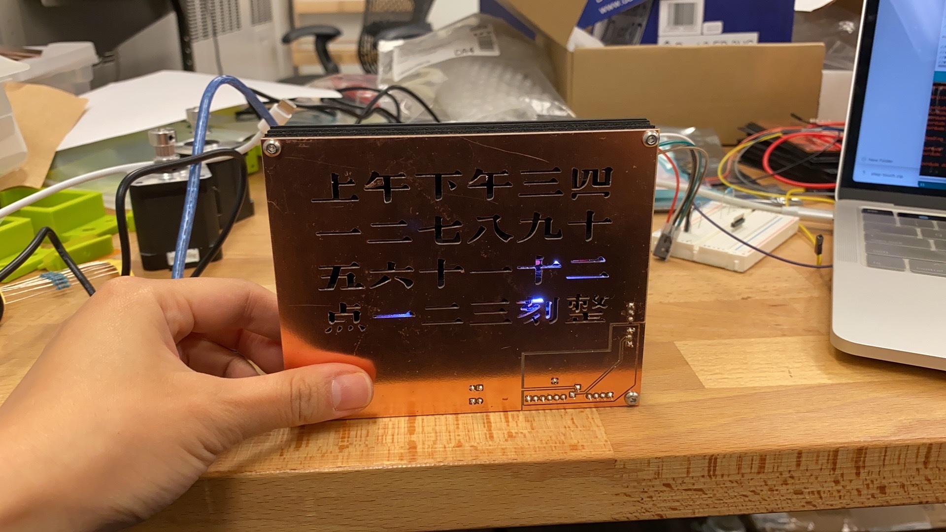
In my design, I made the copper front face the back of my clock surface, and the bottom of the copper is my clock surface. Hence, the Chinese characters are mirrored in this PCB graphics. The font I used is 华康古籍黑檀. I modified the outline so that it can be milled on a board. All the ground pins were connected on the back side of the board to optimize the trace layout. The area outside of the shared ground, which is almost the rest of the clock front face, is connected to a capacitive touch pin, similar to how I implemented that on my jansen walker. The clock will be touch activated on the front face!
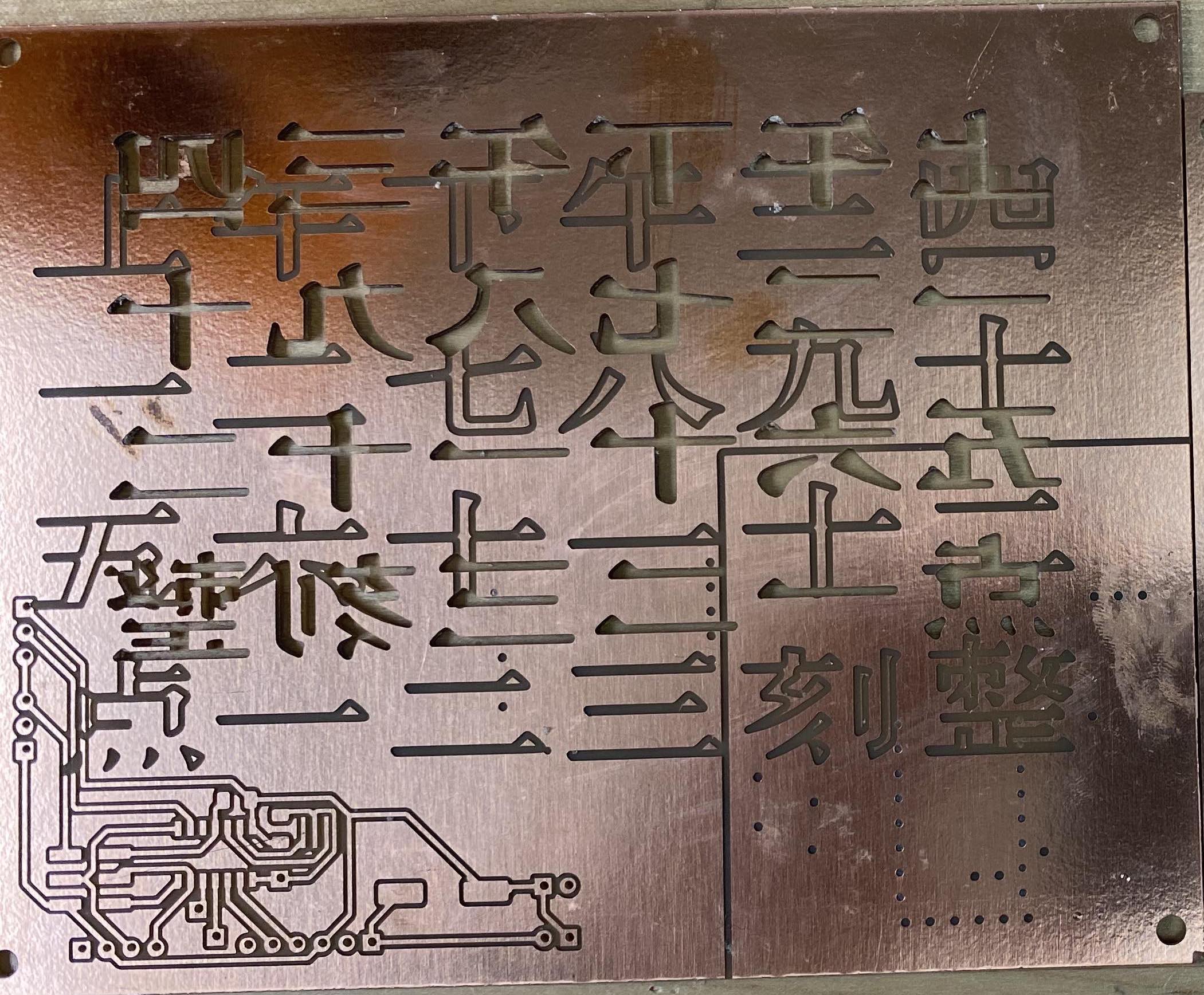
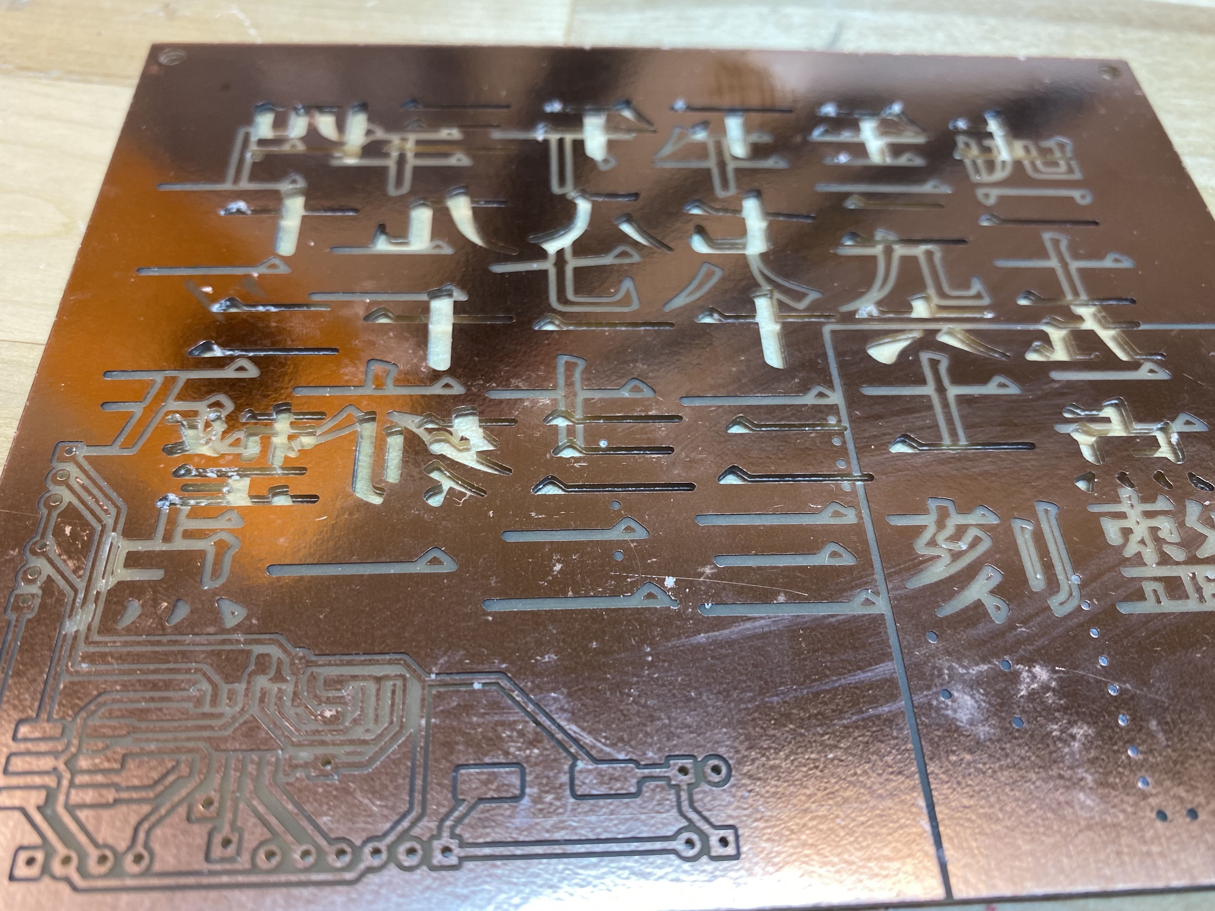
And here are my board. I first got the size of the board wrong so I had a slightly smaller board milled. Then, as we all are very aware at this point, I milled my second board as a backup but ended up liking the size of it. The second board was milled on the sacrificial board of the first board, the traces from the first board are all visible, creating an interesting juxtaposition of different textures of Chinese character. This will be the back side of the clock face.
I left three pins that can read and write diginal input. They were reserved for an analog light intensity sensor but I decided that it did not work with the aesthetics of the clock so I took it off. OK I just ran out of time… The idea was that I can change the color, or brightness, whatever, of the LEDs based on the light intensity of the surrounding environment. It still can be implemented.
One component at a time
We spent last week on serial communication between the milled board and our PC. The same procedure was followed until I can read the analog light sensor. Then I tried to read the capacitive reading and that works too. Both functions were successfully implemented from my previous assignments.
The rest of the time, which is the majority of the time I invested in this prototype, was spent on lighting up the LED and reading the real time clock.
I tackled the LEDs first. NeoPixels use WS2812 as the driver. Unlike the most common 2-pin LEDs, NeoPixels have three pins - Vin that takes in 5V, GND that is grounded, and a signal pin. The firmware will communicate with the driver through the signal pin. I used WS2812.h library. I cut 6 LEDs to begin with, trying to see if I can light them up. It can go wrong in two ways:
- if the LEDs light up in random color, the microprocessor is probably talking too slow for the LED drivers. In my case, the default clock frequency of ATtiny44 is 8 MHz and I think the default clock frequency of WS2812 is probably 16 MHz. When I chose 8 MHz internal clock frequency, the light will have random color that I did not assigned. The strip also did not go through the loop I wrote. They just couldn’t communicate.

At this point, it is somehow successful, but not really.
- if the LEDs are all lighting up but are solid white, the microprocessor is talking too fast for the LED drivers. In my case, I have a 20 MHz external crystal installed to enable serial communication.
The solution to either problems is to change the communication frequency either in the library or in the firmware file by adding this line:
#define F_CPU 20000000UL
and including TinyWireM.h library. This library makes sure that both WS2812 and DS1307 can work with ATtiny microprocessors.
The next step will be reading the time. Here is a lesson that I learned hard - I tried to find some tutorials or other’s project documentation as a starting point. There are only a few I could find online. So I cherished them so much and tried to replicate their results. I shouldn’t have spent so much time on that. They used slightly different microprocessor such as ATtiny85, which has twice as large as flash memmory as ATtiny44. I just couldn’t figure out what make theirs work but was not working for my project. I even tried to modify every possible library I found for DS1307 and WS2812 but that is going to no avail.
My advice for future me, or you, is: start from a reliable library and use their simplest example code. That’s it. Instead of modifying other’s code, I just added the simplest command to read the hour and minute of now to an empty sketch and it worked. Here, I’m printing the values of hour and minute to the serial port. It was like an eureka moment.
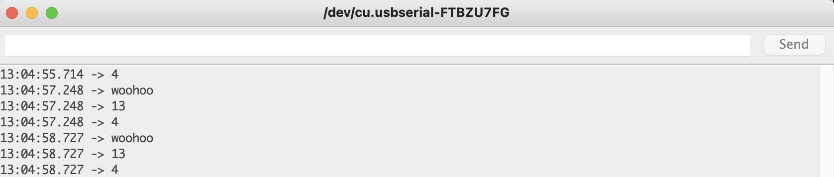
Then it’s time to connect everything as a system. I took out serial communication at this point once I knew I can read and use time and I also have capacitive touch sensing. Again, after spending many hours to no avail trying to modify other’s project code and looking into all libraries I can possibly found for WS2812, I eventually used the simplest example sketch that came with the library WS2812.h to light up the LED that corresponds to the hour value (it was 2 AM in the morning, and LED #2 would be the third LED).
Woohoo! At this point, the hardest part for my adventure in this project was done. The rest will be small tasks.
Mapping LEDs
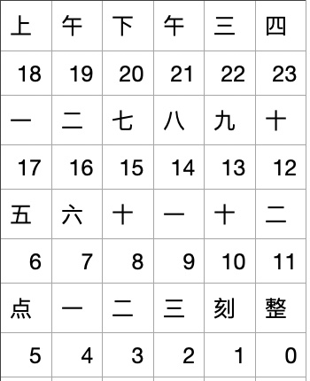
When talking to the LEDs I found that I cannot control more than 18 LEDs. I have 24 characters to light up, so now I just have to abandom or combine some of them. Since the two digits in 11 and 12 will light up at the same time, they can be made into one pixel. I took out the function of showing wether it is AM or PM. That’s 18 pixels. I translated the characters into numbers and English:
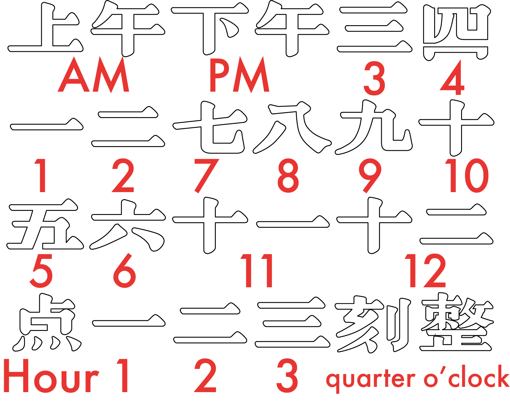
The LED pin on the board is close to ‘o’clock’, so that will be pixel #0. #8 and #9 are finally #8, #10 and #11 are finally #9, #18-21 are taken out, and all numbers are adjusted accordingly.
I tested the code when the LEDs were still in a strip.
LEDs #1, #3, #5 lighted up, which corresponds to ‘2 quarters past some hour’. The hour value is not showing in this gif, which means it was probably 3 or 4, which are LED #16 and #17. Then I cut the strip and placed the LEDs in their corresponding slots.
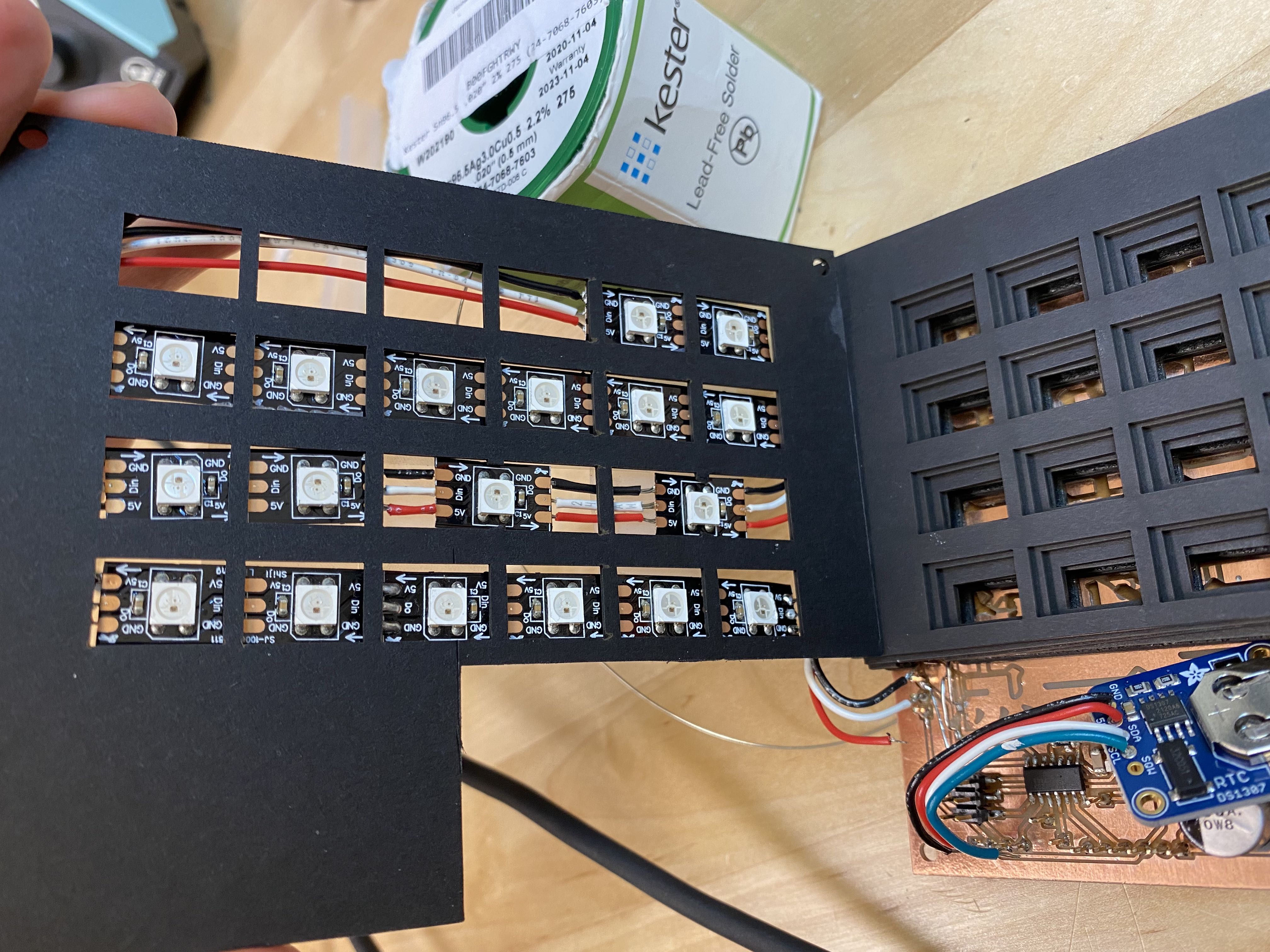
I also soldered the real time clock breakout board.
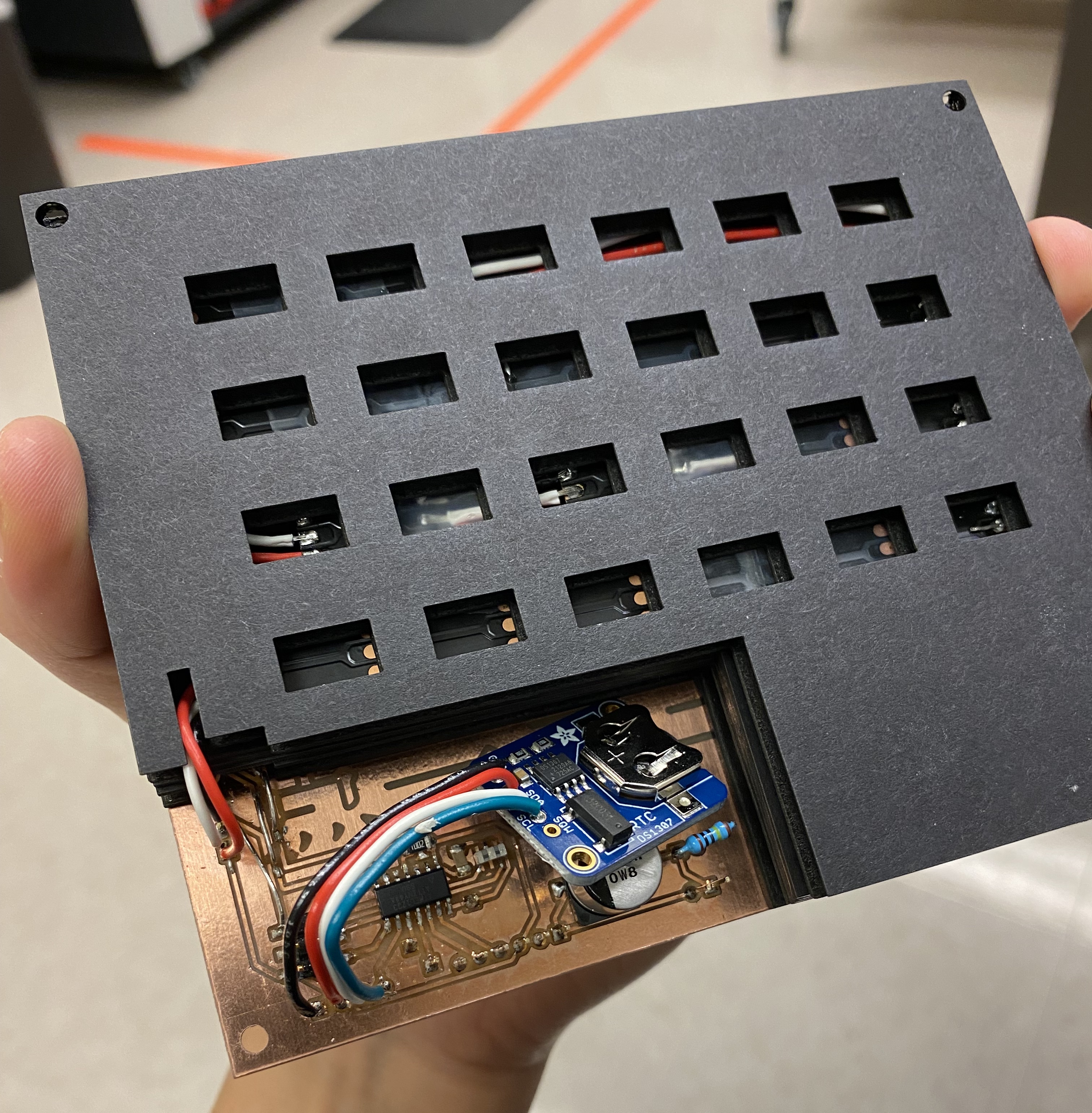
I assembled the spacer layers and the backing and screwed everything together. If you check from the mapping, this clock, at its first fully assembled and working moment, shows ‘1 quarter past 12’. Since the time is not exactly accurate, a quarter past 12 covers 12:15 to 12:29. The LED beneath ‘hour’ was not lighting up. In Chinese, when we express time, we always include ‘hour’. After changing the firmware to light up ‘hour’ whenever the clock is touched, it was exactly 12:30 for our final presentation and I have something to show.
Demosssss!
During class presentation, my peers and my instructor suggested that I add a layer of something, as simple as white paper, to diffuse the light a little bit. I also caught some small bugs that only showed up when the time has come (for example, I mapped ‘5’ and 6’ to the wrong pixel indeces and I can only find out about that at 5 or 6 AM/PM). The current version has fixed all that!