This is the last assignment before the grand project. This week we are making a double-sided PCB that has a shared ground on the back and can communicate using serial port.
In the lecture, we learned about how serial ports beat parallel ports historically. From the time that I started to familiarize with physical computing, I’ve done all the communication with serial ports, mostly USB. But from this course, I learned that there are other ports or connections or ways to establish communication between our personal computers and microprocessors, eventually between microprocessors and microprocessors.
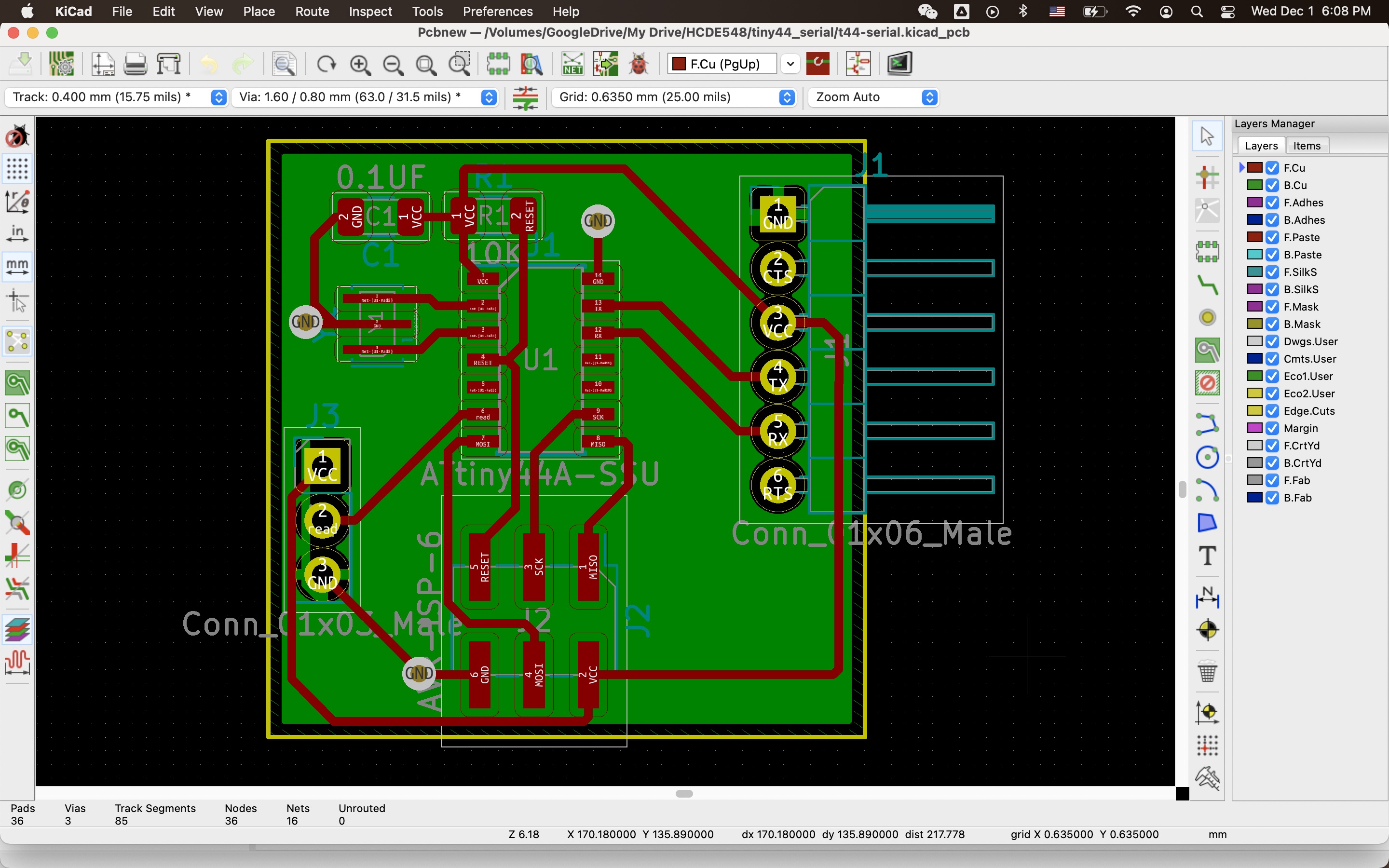
We are given a board design that has 6 pins designated to communicate with a computer through a TTL to USB serial converter. I added three pins which connect to a breakout board of analog light sensor. I plan to use this in my final project so this assignment doubles as a chance to test one component.
It’s a double-sided design, which complicates the milling a little bit. The trick is that the board needs to be aligned to the corner of the platform perfectly. Some tolerance is allowed, as long as the through holes stay on their spots and do not cross two adjascent copper traces. My first try was a near miss:
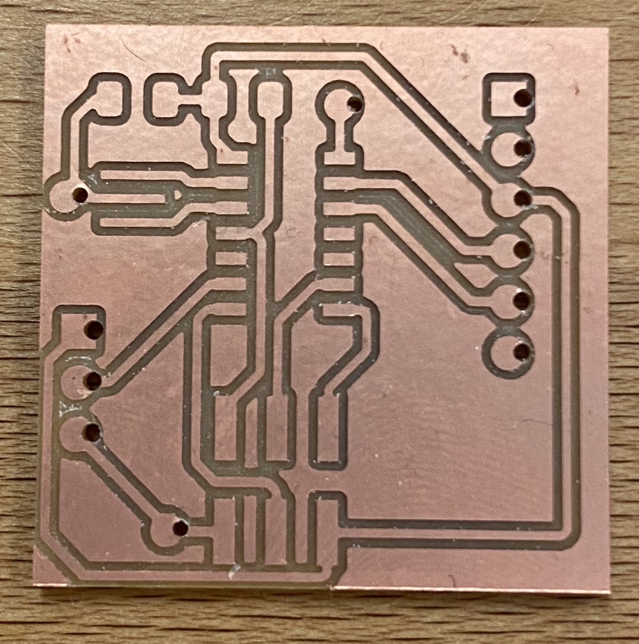
I think it would still work, but as we all know, always mill a backup.
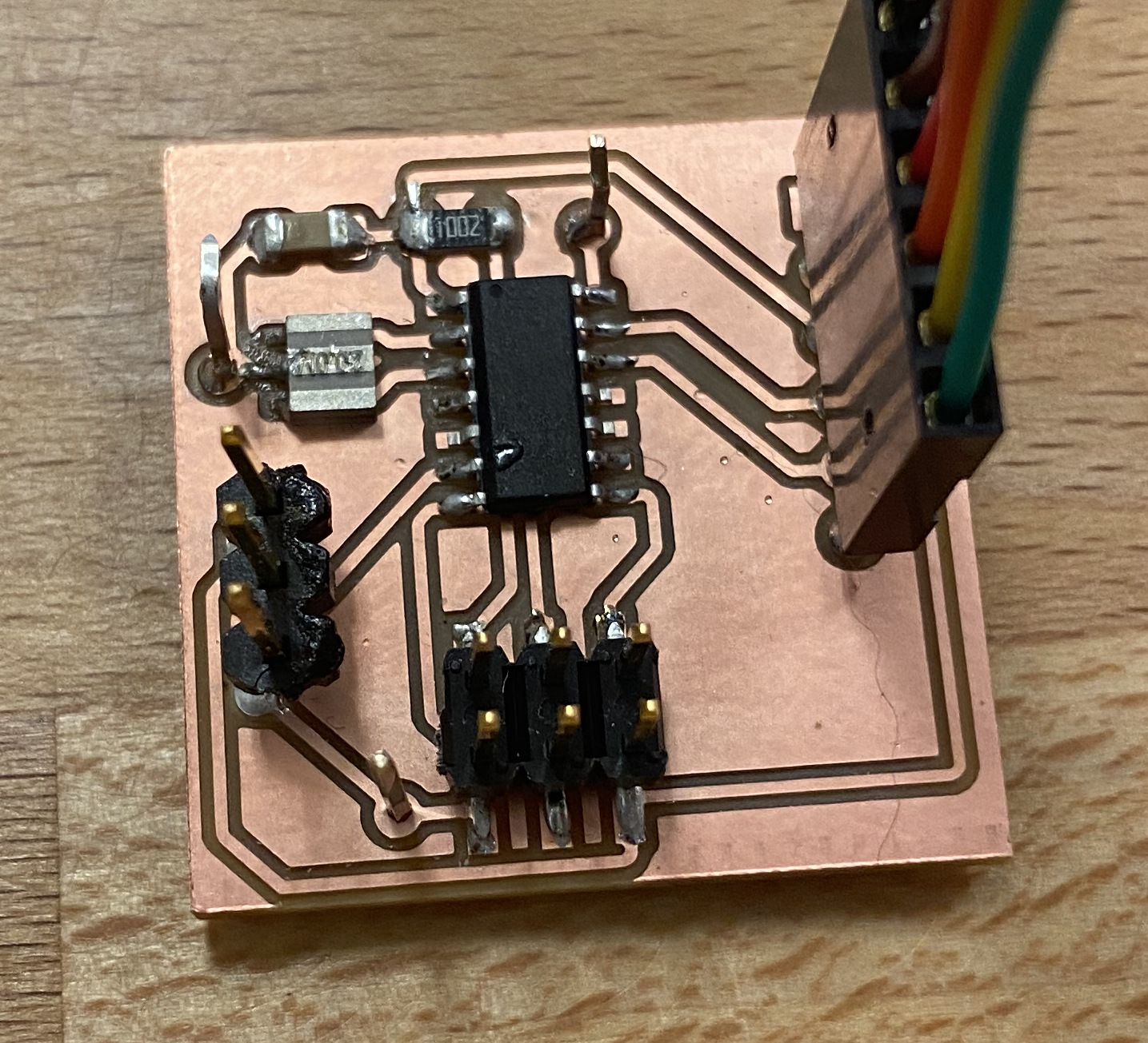
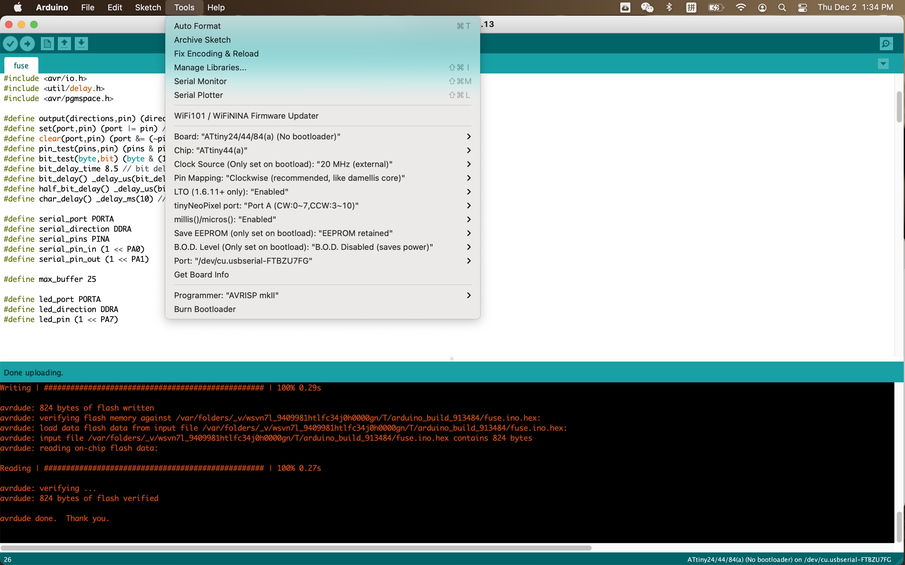
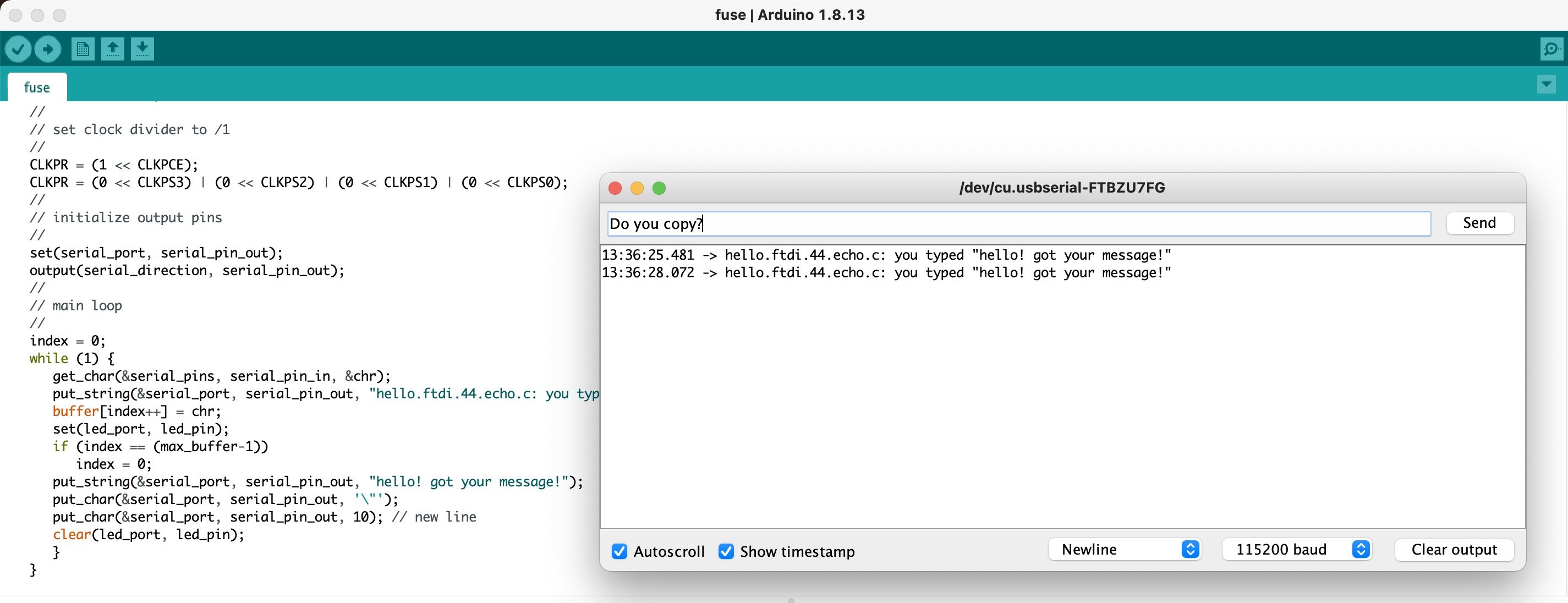
I struggled with flashing the board and programming the fuse. Fuse enables the use of an external crystal which subsequently allows communication between an ATtinny44 and a PC. After figuring out how to properly solder vias, my board can communicate with my computer with the example code Nadya provided. Since I lack certain proficiency in C (OK I don’t know how to program in C at all), and considering the complexity of integrating all components next week, I spend some extra time trying to use Arduino to write code and flash the board.
Set up the programmer, an Arduino Uno board, in the Arduino IDE as below. The important thing is that the Clock Source should be 20 MHz (external). Note that the picture shows AVRISP mkII as the programmer but I actually used Arduino as ISP. Details in previous assignment.
Now we are communicating, but the input is actually my computer’s keyboard. So… what are we doing here? We need another input device.
After staring at Nadya’s code and a simple example sketch for analog read for a really long time, and I eventually came to an epiphany of adding a few lines of Nadya’s code to my code and it worked!
(The number increased when I shone a flash light on the sensor directly. Our ambient light intensity reads 50 to 60 with this sensor. The values range from 0 to 1023. Why did I not include a video of me doing that in real time? Where does that flash light come from?)
Some related files: