For final project, I’m building a micro-brewery with continuous flow!
project scope
I’m recently into home-brewed beer and want to do more experimentation. However, monitoring reaction conditions and ingredient amounts is very labor-intensive. I am building an integrated micro-brewery that can automate ingredient transfer, product transfer, reaction condition monitoring, and experiment logging.
For the final project to be finished in this class, I’m using digital fabrication techniques to make the hardware prototype.
skills
To create my prototype, I use the following skills we learned this quarter:
-
Laser cutting
-
Rhino
-
CNC milling
-
3D printing
-
Incorporating stock parts
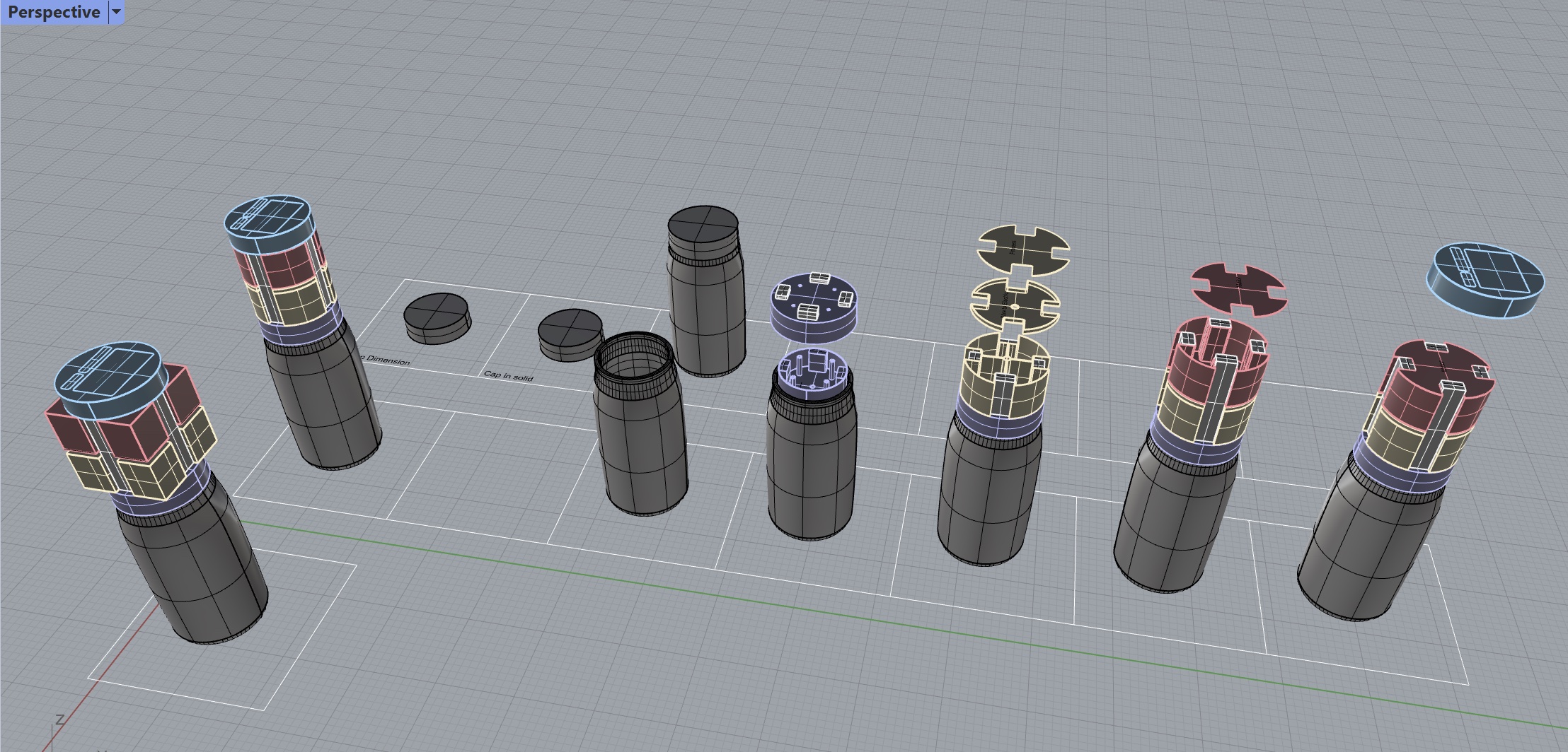
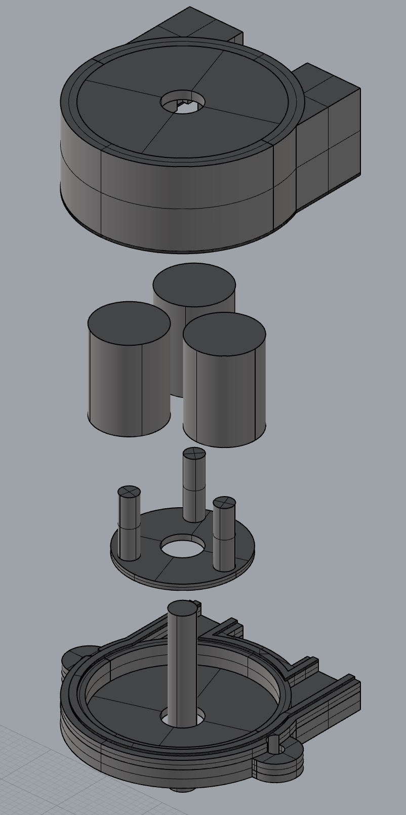
modeling
I’m sticking to my plane to have modularized cap layers designed for different functionality.
I bought stock parts including a glass maison jar, sensors, and motors.
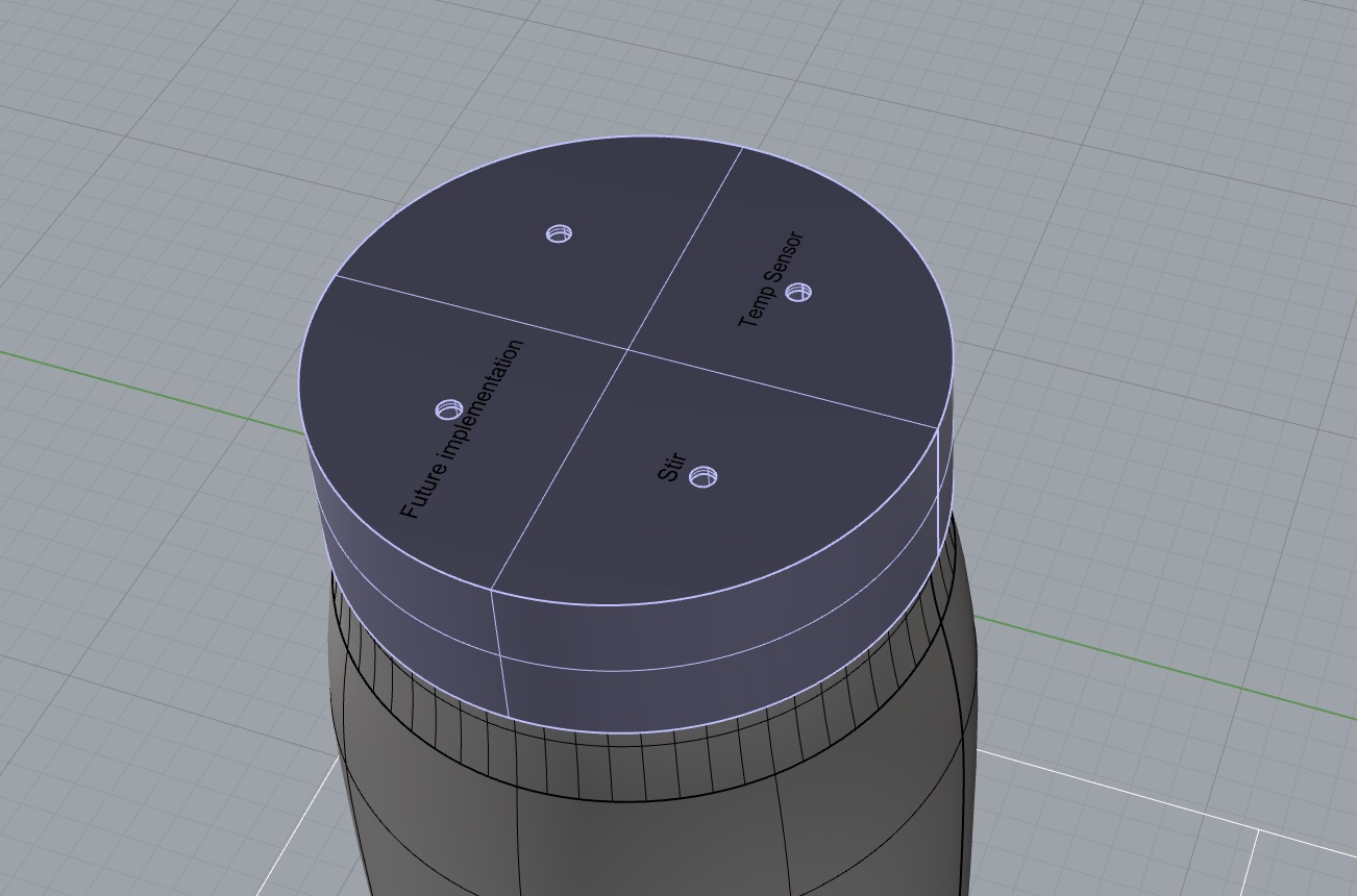
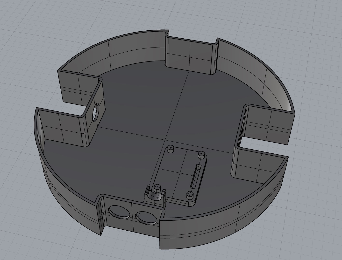
layer 0 - cap
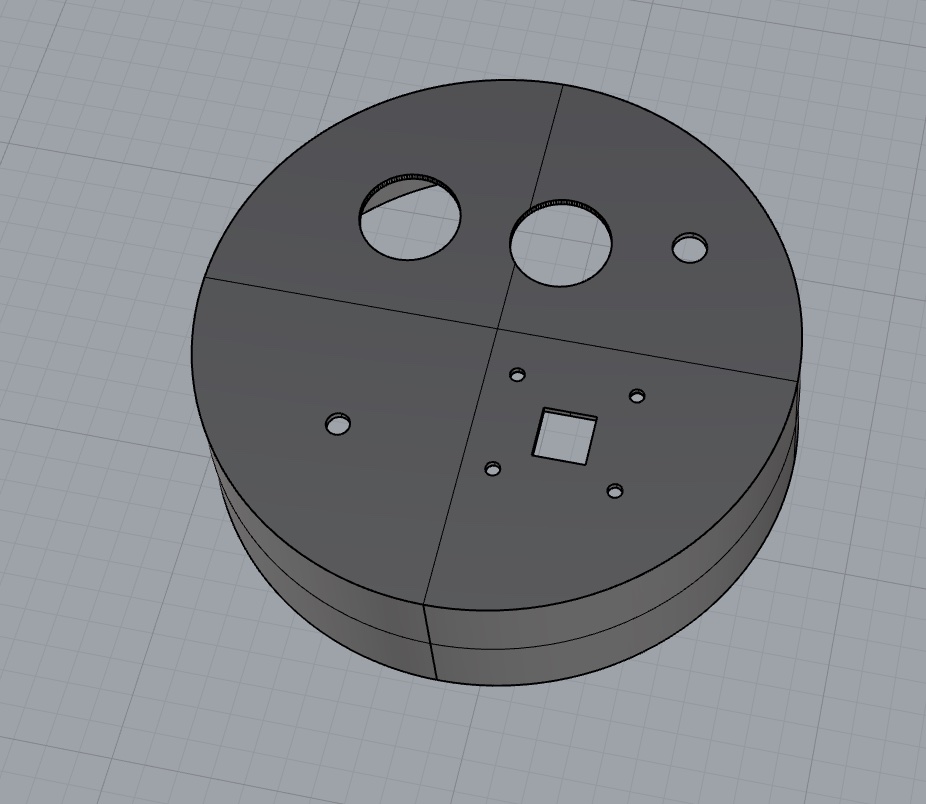
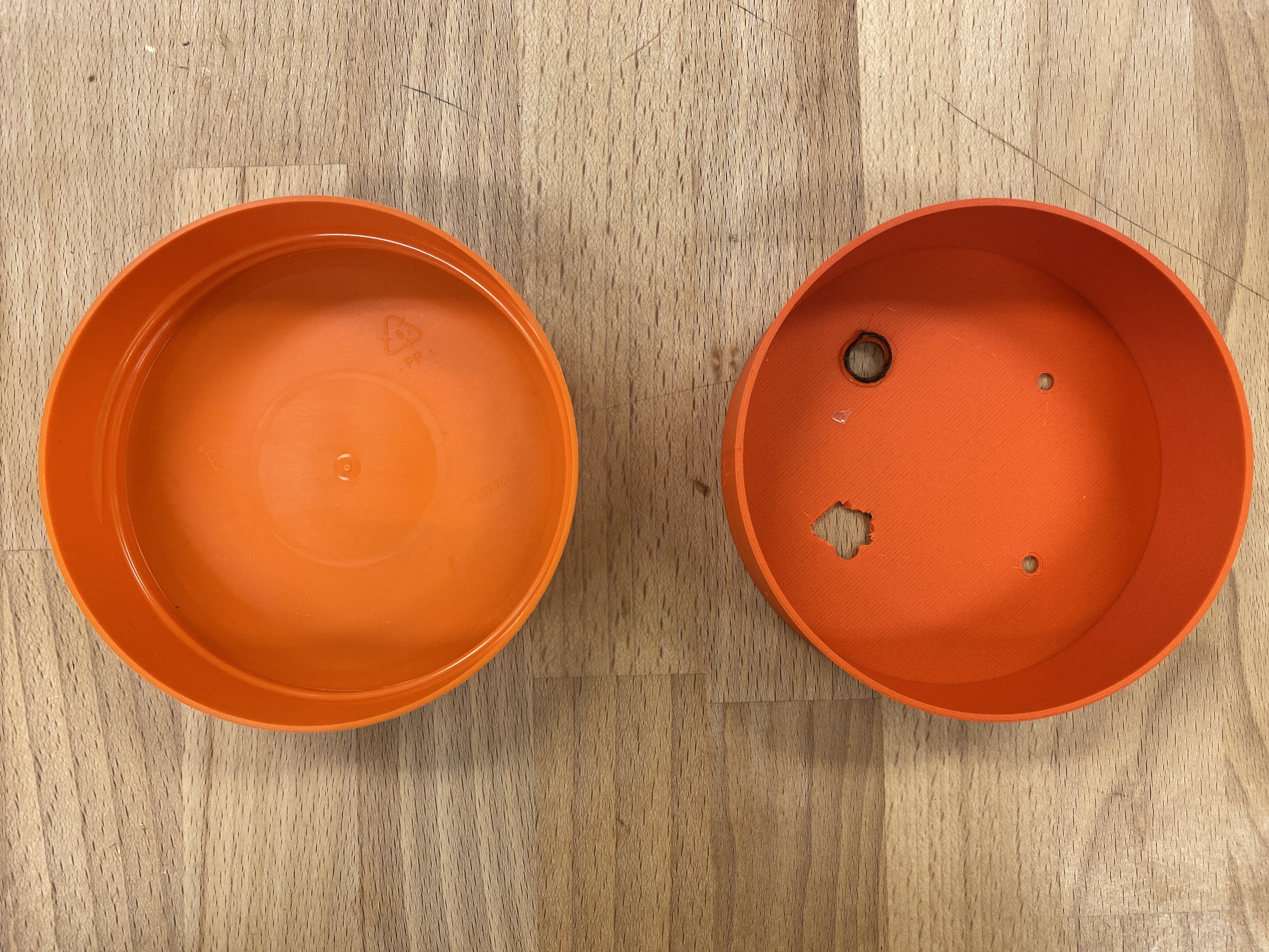
The glass jar is the container for bioreaction. First I need a cap to close it. Originally, I planned to have equally sectioned modules and standardized insert size, but later I figured I need different sizes of holes to allow sensors and motors to come in to the jar. The model was hence revised to accommodate design decisions.
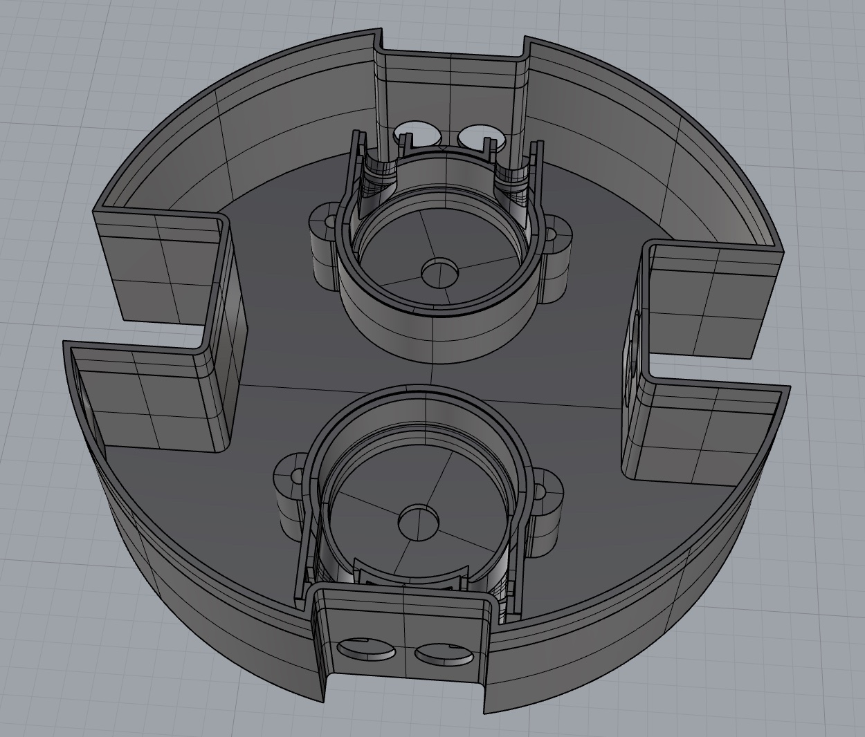
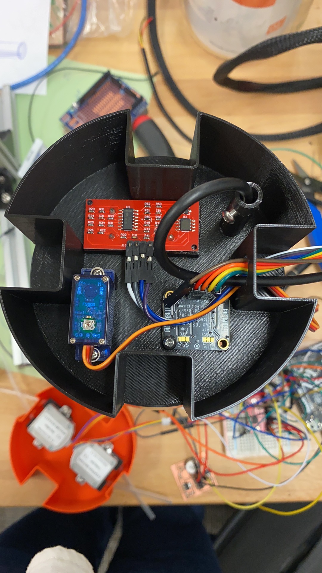
layer 1 - sensing
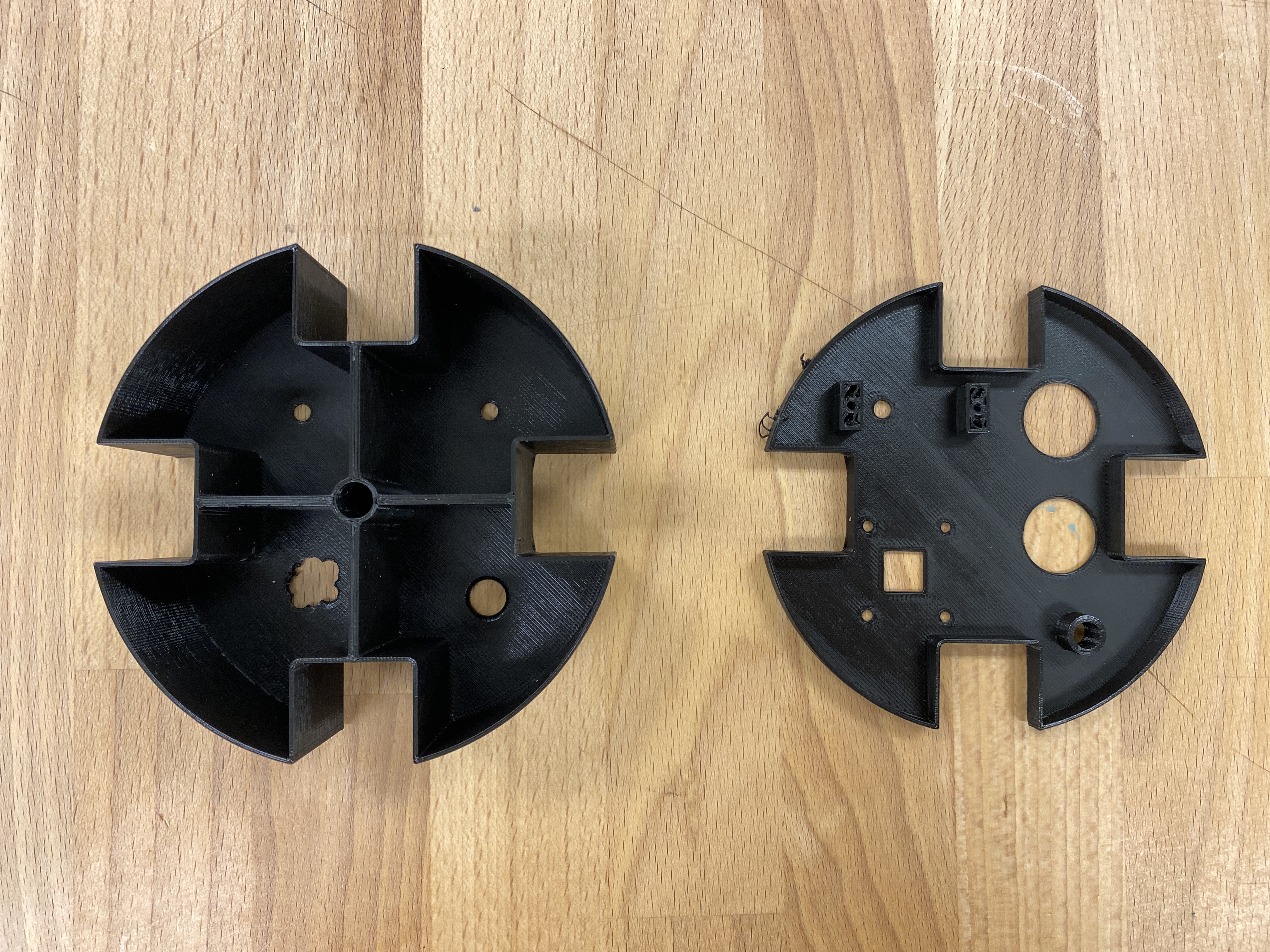
The layer right above the cap is the sensing layer, because some of the sensors need to go into the jar to monitor the reaction condition. It was intended to be modularized, having equal area and the same shape for each sensors. But some of the sensors I have in my hand are larger than the other, requiring more space to fit.
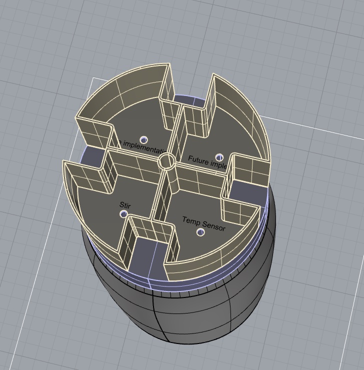
So I first 3D printed this design and tried to stuff all sensors into each compartment. Then I laid out all the sensors according to the actual space they need to take and modified the model in Rhino.
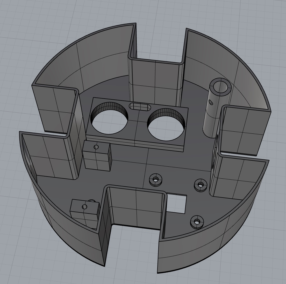
layer 2 - pumping
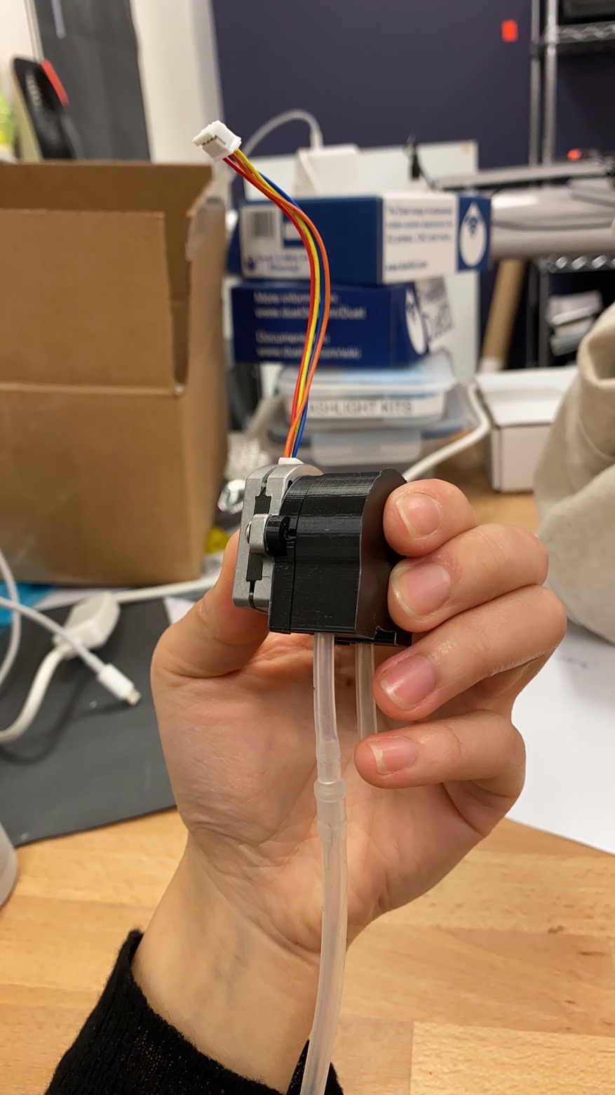
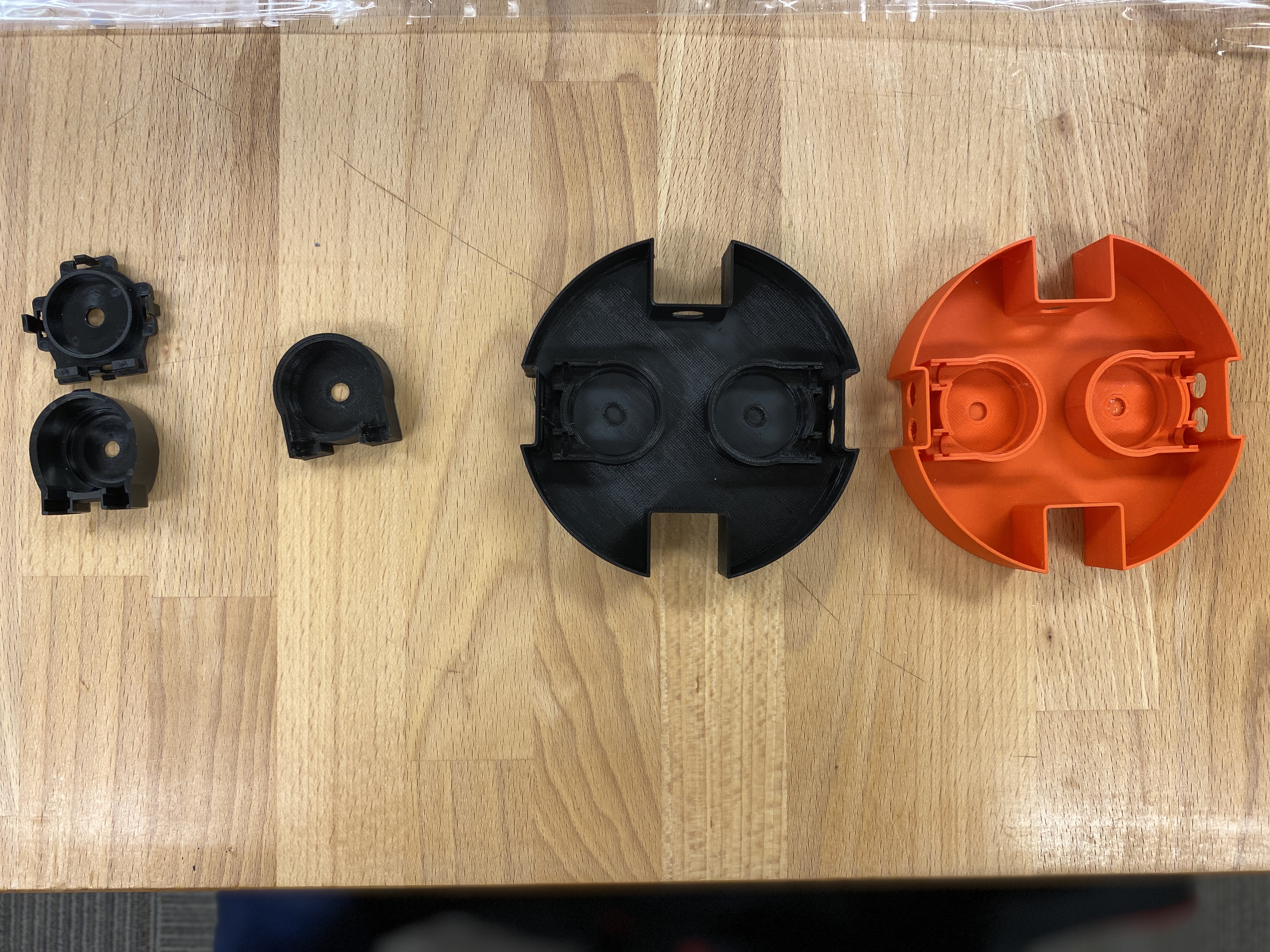
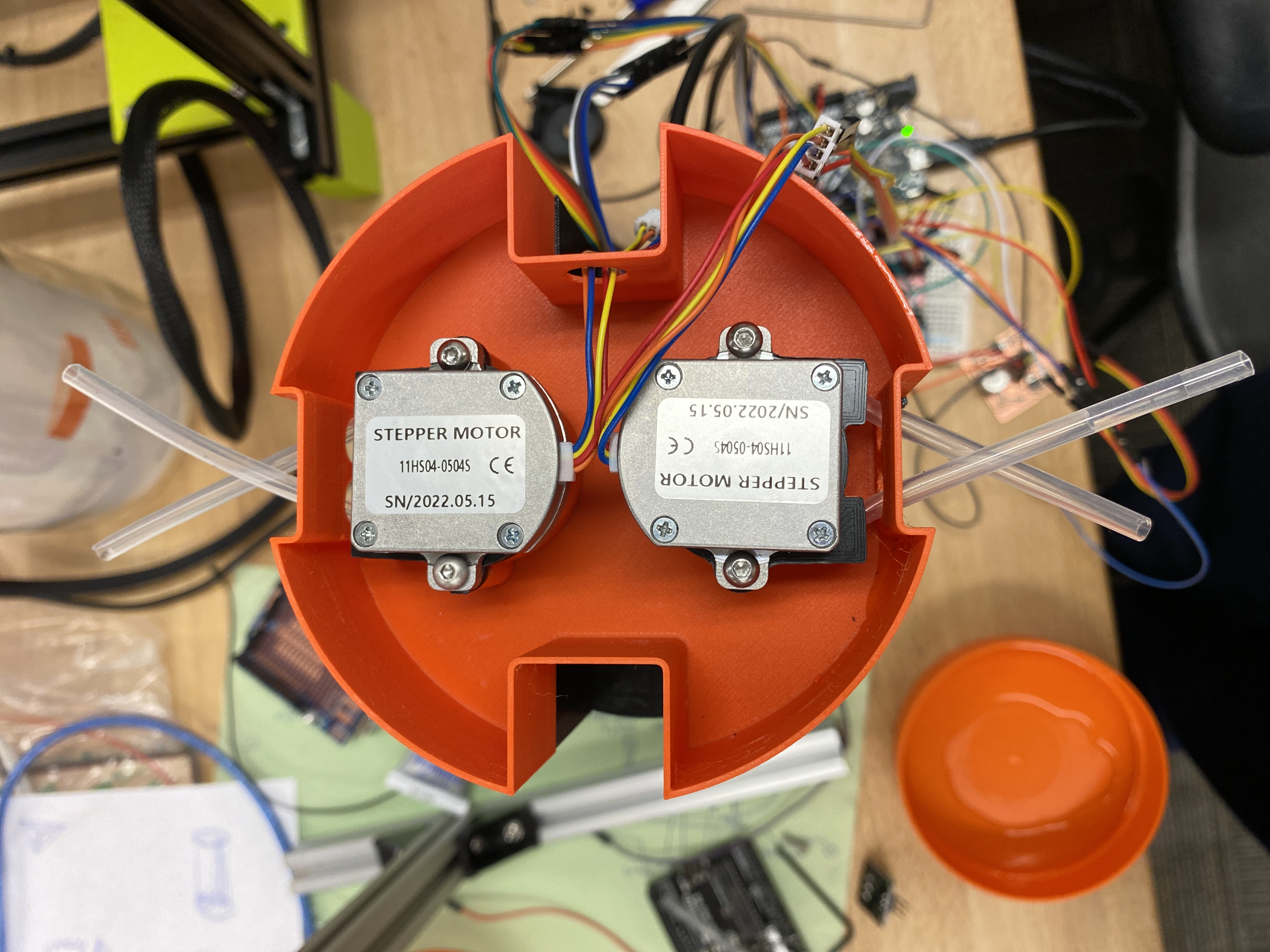
Right above the sensing layer is the pumping layer. These pumps are peristaltic pumps, they feed liquid bidirectionally and the liquid only goes inside the tube (minimum contaimination). I disassembled an off-the-shelf peristaltic pump and designed fixtures so that I can use a more precise stepper motor to drive the pumps. And the new motors are much smaller than the ones in the stock pumps so I can fit more than one into one layer.
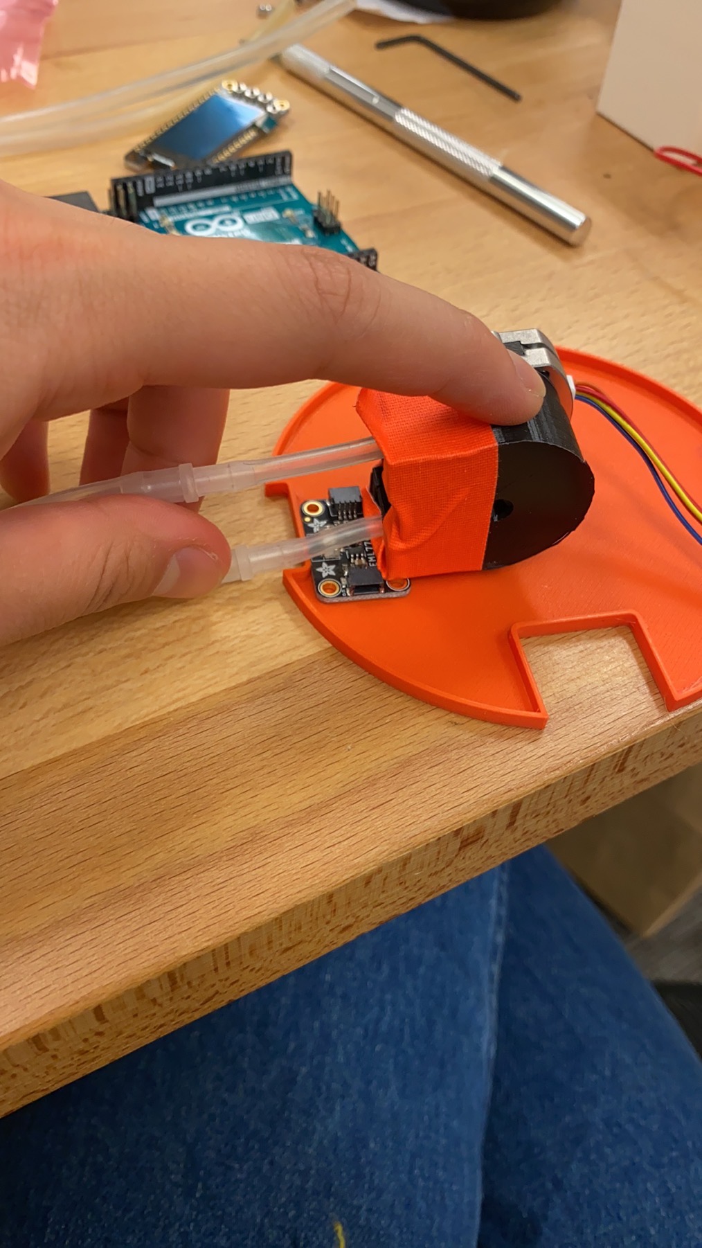
layer 3 - analyzer
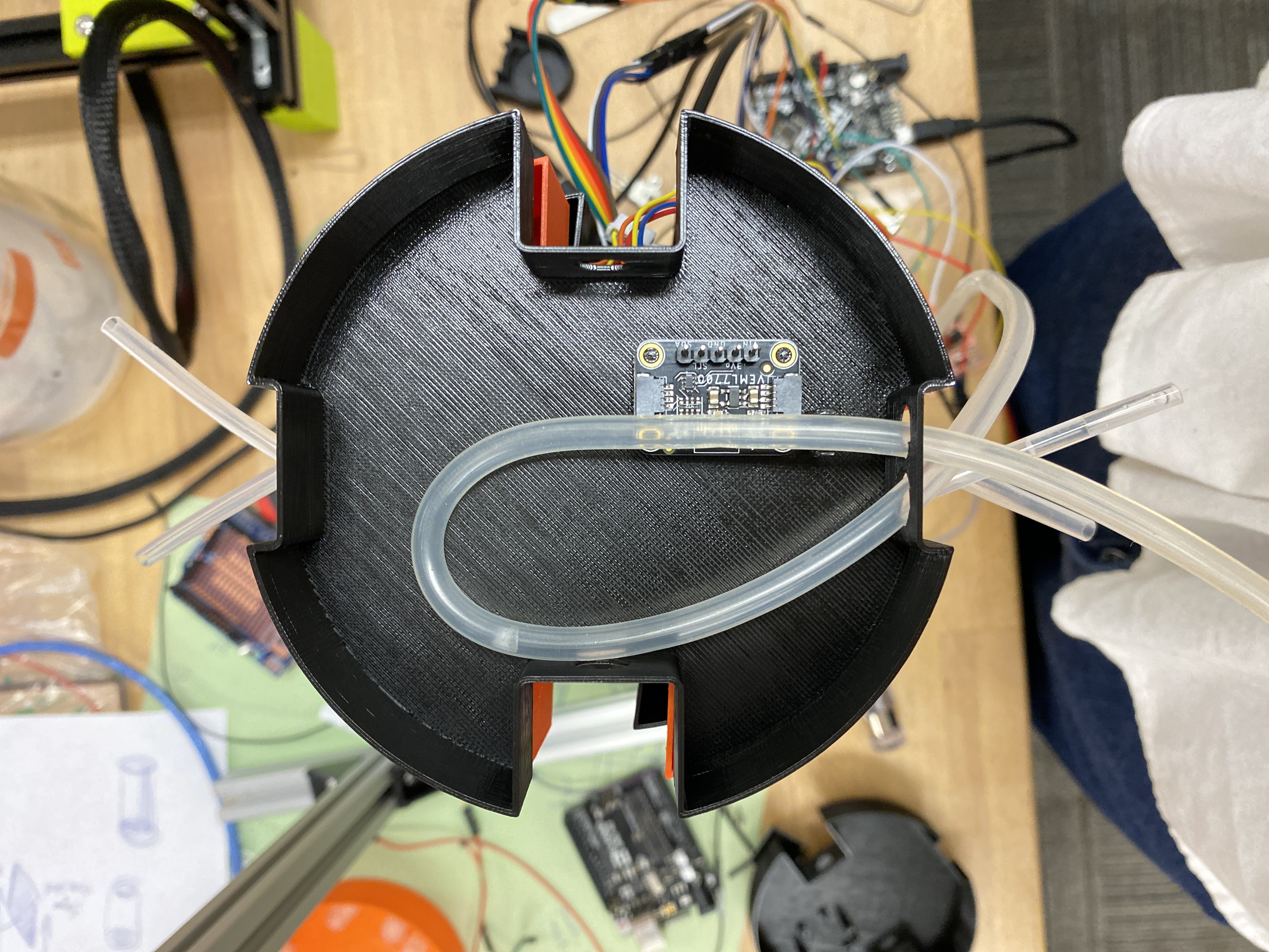
The last layer contains only one sensor, an ambient light sensor that monitors color change. For beer brewing, one of the metrics for evaluating the readiness of a batch is the color of the liquid. One of the pumps will feed liquid to this sensor.
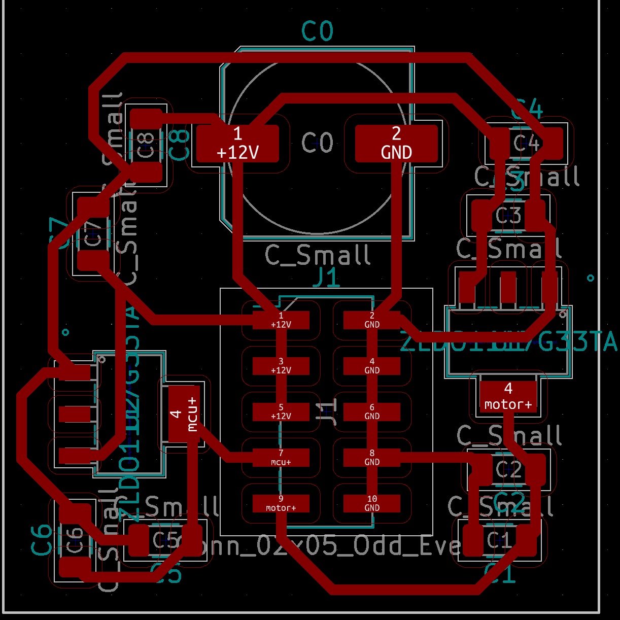
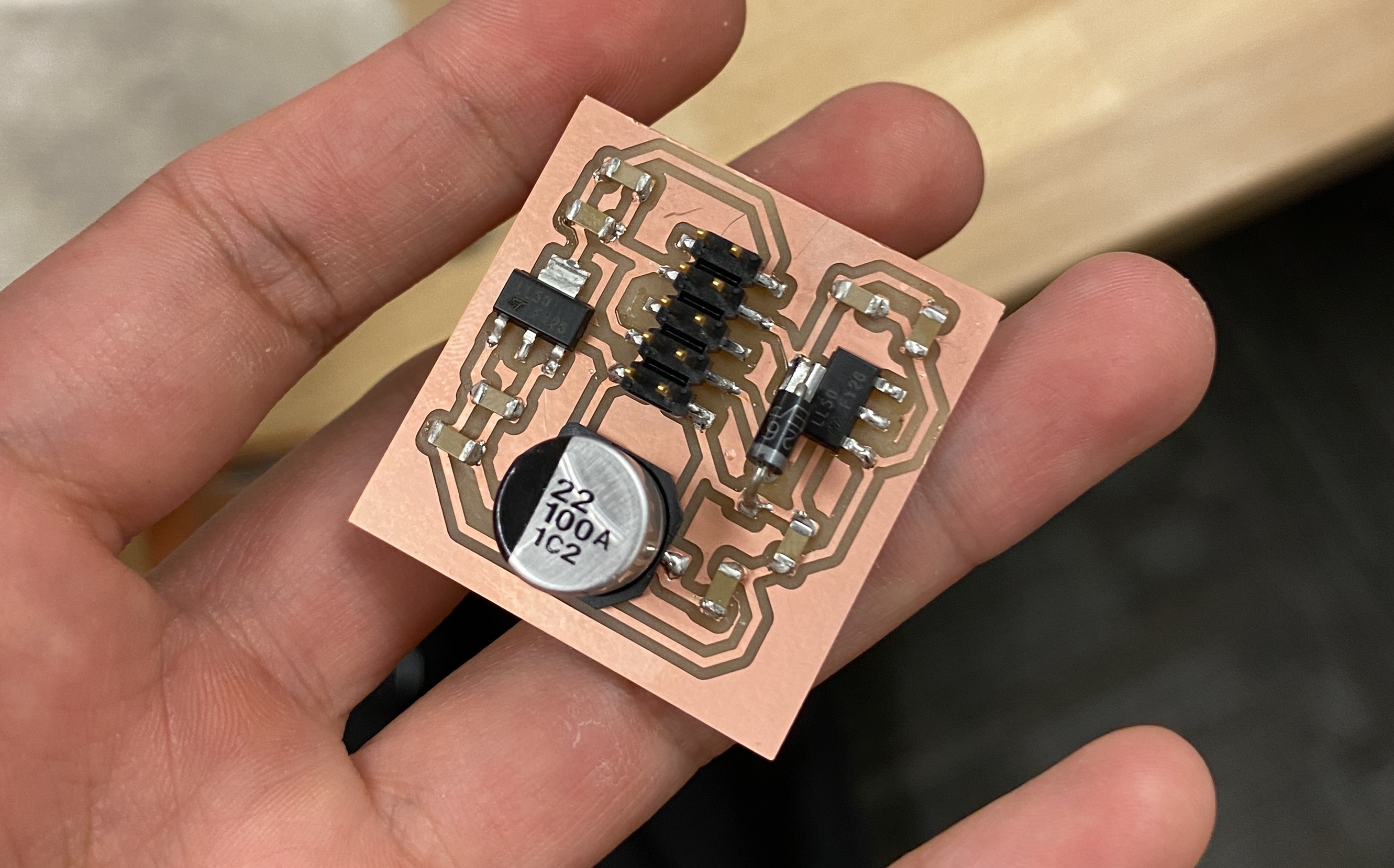
I also used KiCad to design a voltage converting board to power all my motors and a microcontroller. It is milled on the Othermill.
prototyping
It’s time to print and mill!
Starting with the cap, I iterate once on the design. The left is the original cap for the maison jar. I used a soldering iron to drill holes on the 3D printed cap so that I can refine the design.
The sensing layer actually share all the holes with the cap.
This sensor is the reason that I had to abandon the original 4-compartment design because it won’t fit inside of one compartment.
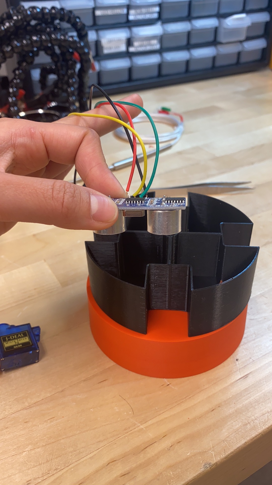
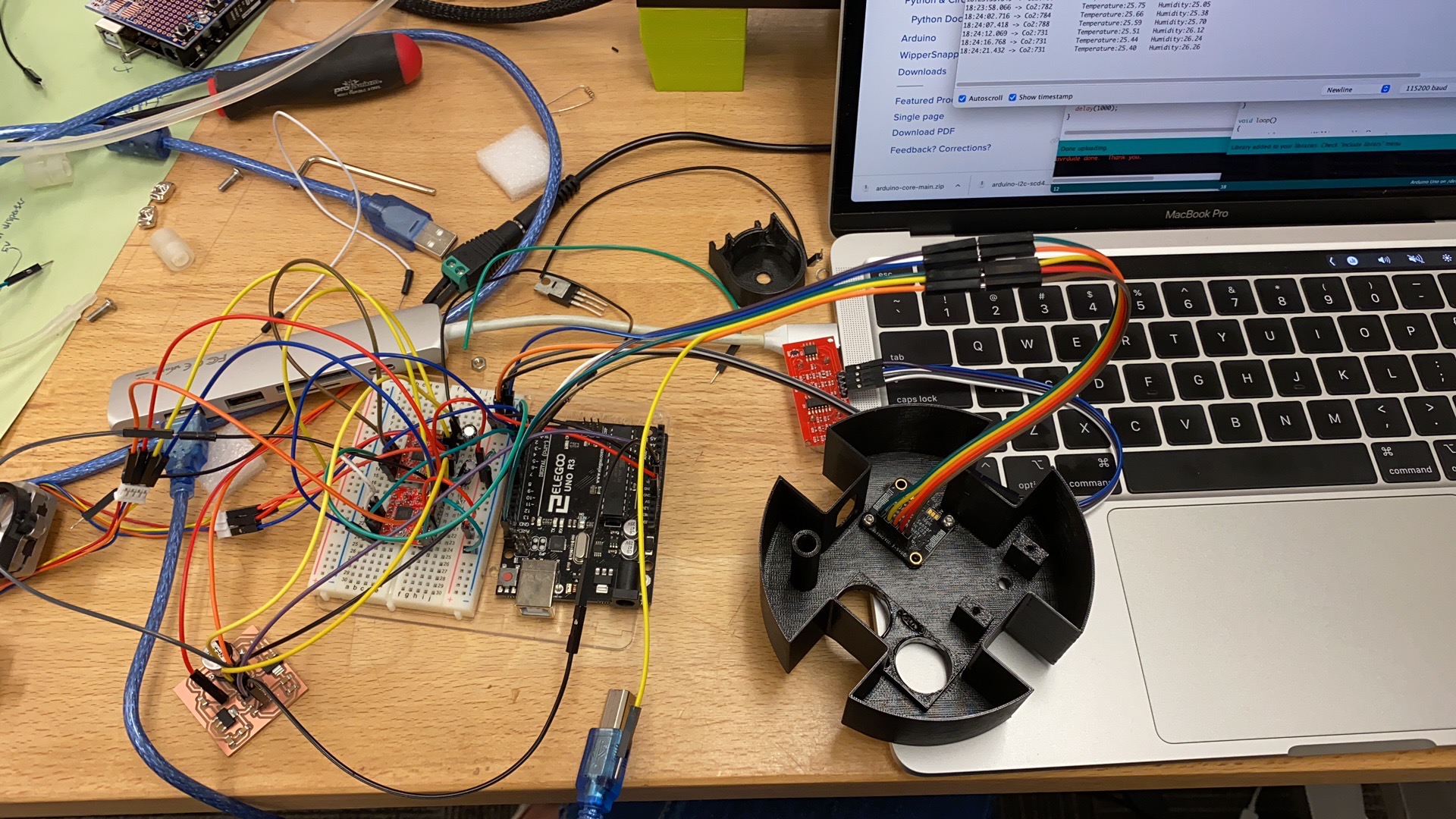
Then I placed all the sensors on their spots and tested if they worked with Arduino code.
The pumping layer takes a lot of time. I first replicated the peristaltic mechanism using a different motor and made sure it works before printing the whole layer in one piece.
Trying to eyeball how many motors can fit into one layer and their placement.
Once it worked, I made the whole layer. The left-most parts are from the original stock pump.
Both worked!
Now comes to the last layer with the analyzer in it. This took one iteration as the original placement didn’t consider wiring and the tubing is in the way of the electric wiring.
For the board I milled I also had one iteration, because all the parts use different voltages.
Now! Stack them up!
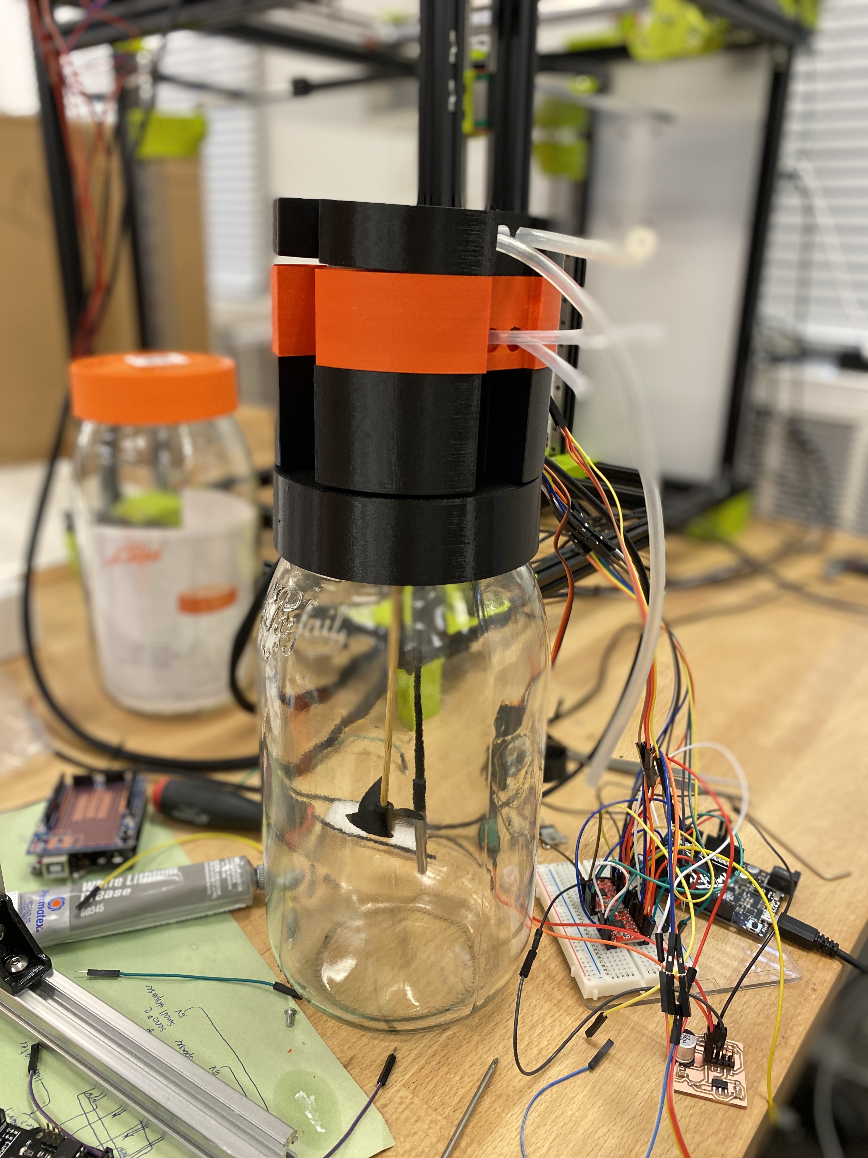
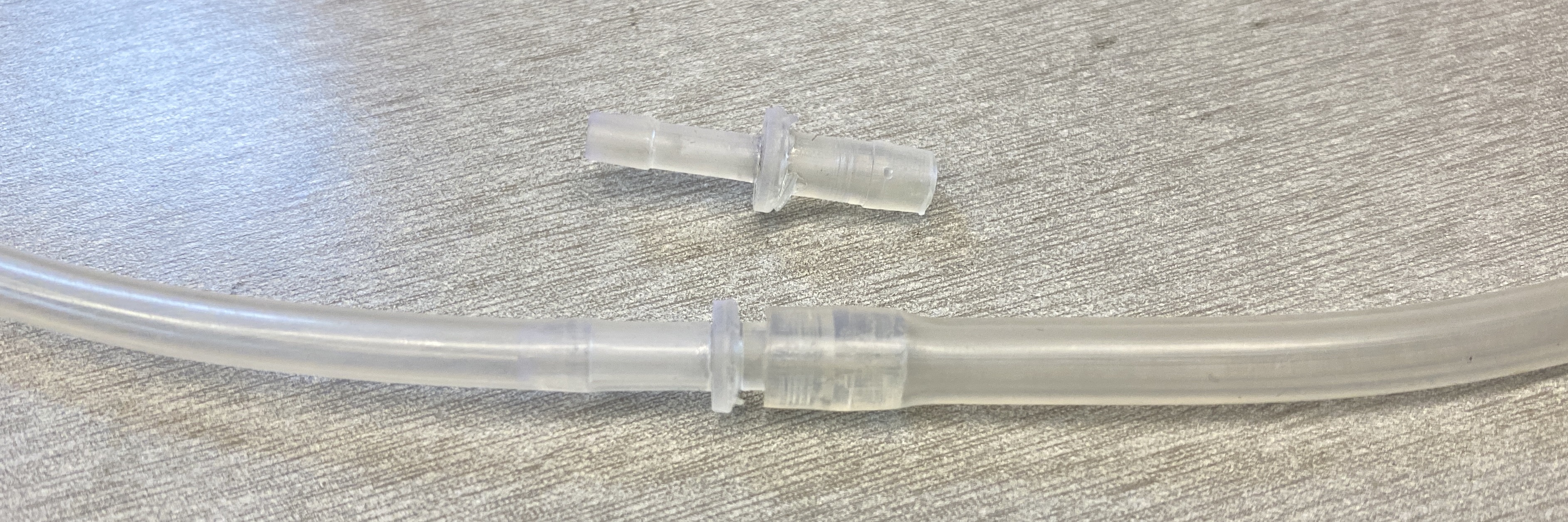
I also modeled and 3D printed pipe fittings with SLA 3D printer.
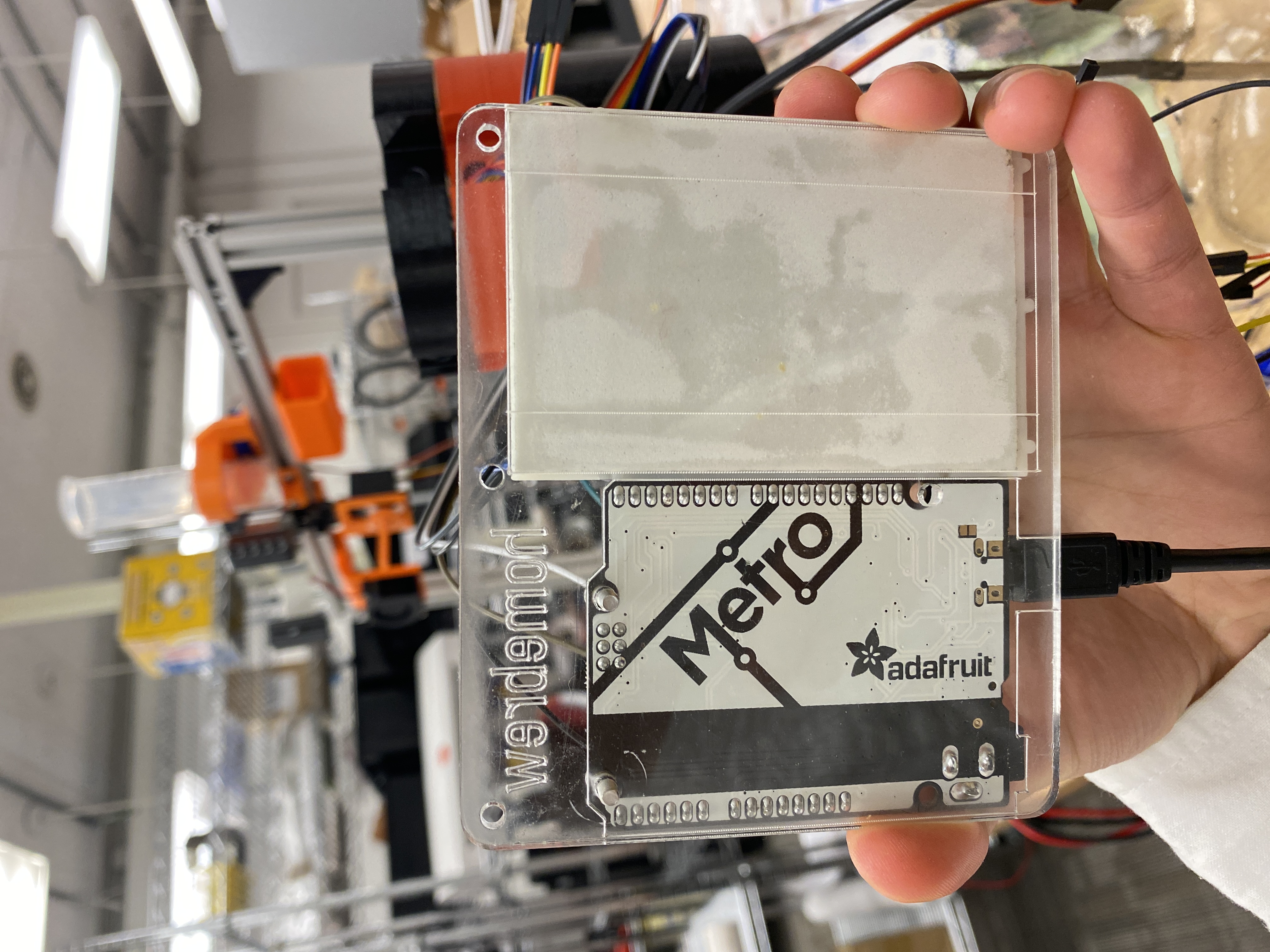
For the wholesome of the system, I laser-cut a piece of acrylic to hold the microcontroller and breadboard together.
future work
To actually run it, I will spend more time on writing the firmware for the microcontroller.
All files: