I never watched Ghostbusters.
This week we are making modification to a board design that uses ATtiny44 as the processor by adding an input and a output device. The milling process is documented in last week’s post. We use KiCad to design and modify our PCB.
Design
I want to have a moisture sensor to the potted plants I own to keep them from drying out or draining. There are a lot of good examples (such as this and this) and product-level design out there on the internet as inspiration.
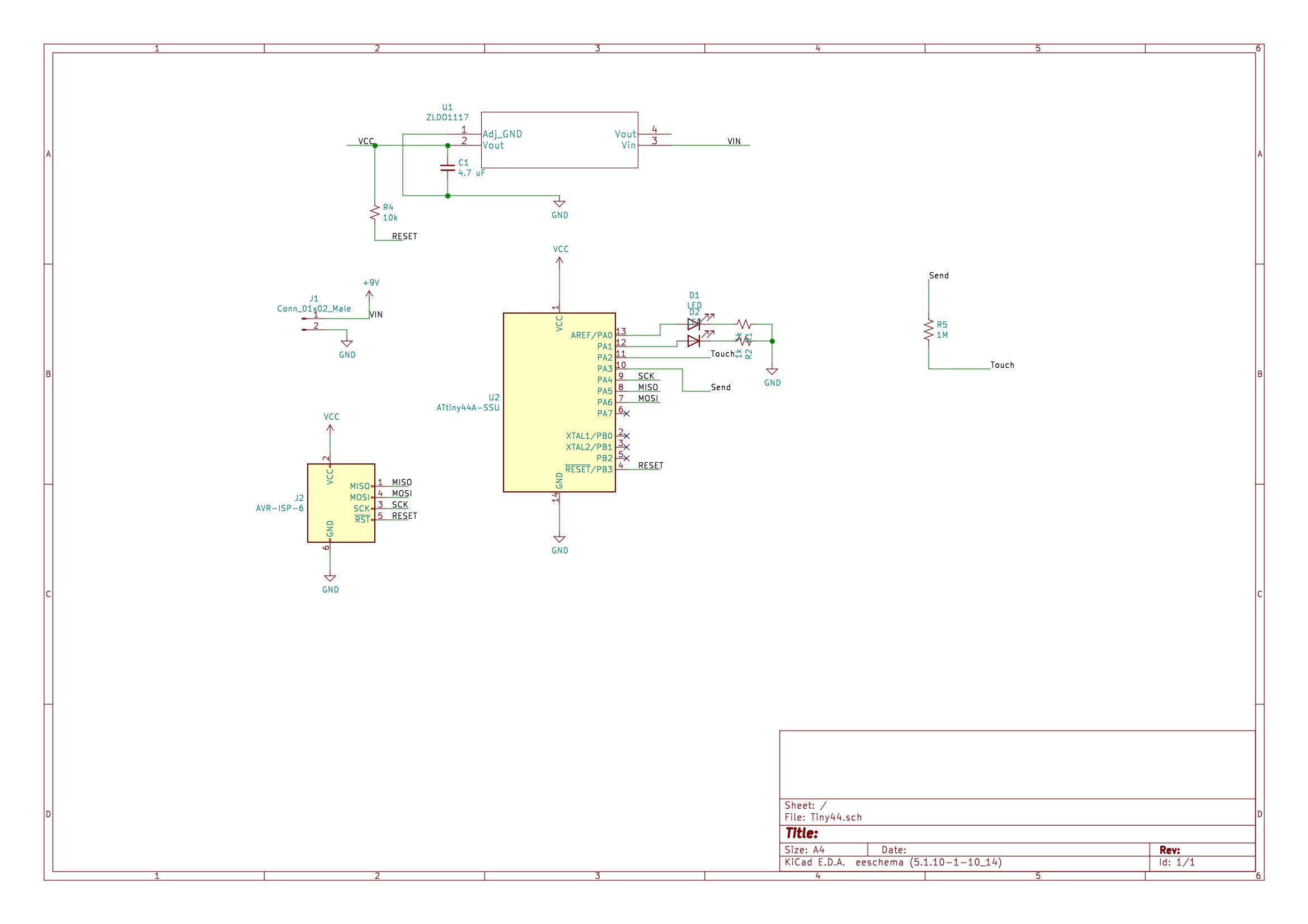
As Nadya explained in-class and some tutorials showed, essentially it is a capacitive sensor. Two digital pins will be needed to transmit and receive signals that are also connected by a large resistor (ideally 1M ohms). As a capacitor (in this case, my hand, your hand, moist soil…) approaches and touches the signal-reveicing pin, the capacitor dessipates charges and the receiving pin will know the drop.
These pins will be pin 10 and pin 11 as shown in the schematics.
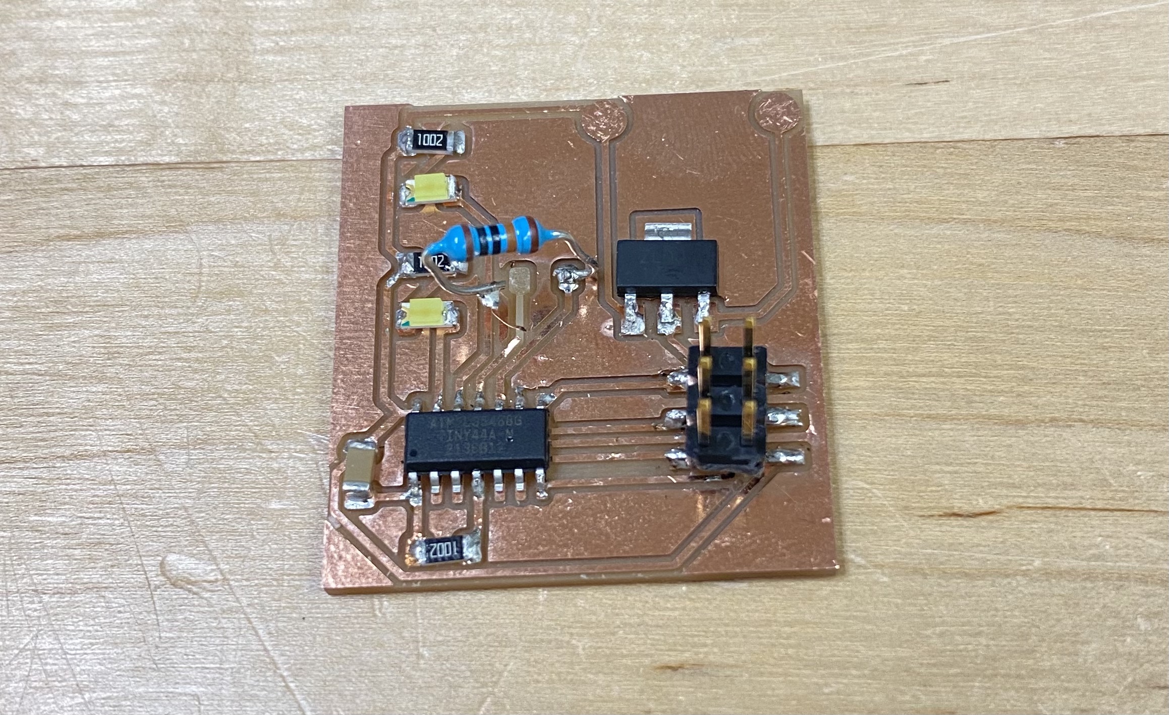
I made a test board to justify my soldering skill. And apparantly the first one, like pancakes, is always a throw-away. Nadya helped me figure out there is a 1000 Ohms resistance between ground and VCC, meaning the board is shorted somewhere. That’s the first problem.
Second problem - I soldered 10K resistors in place of 1K resistors as current-limiting resistor for LEDs.
Third problem - I soldered the wrong regulator. The current-limiting resistor is calculated based on a 5V VCC.
These problems were fixed in the next and final PCB fabrication.
I decide to go with a ghost cutout because then I can make the two LEDs its eyes.
Talking to the programmer
We only have one AVR-ISP MKII programmer to share among all the classmates, and also I am more familiar with Arduino IDE for programming microcontrollers, so I decide to try to communicate with ATtiny44 via an Arduino board in the Arduino IDE. I used Uno and there are a lot of good tutorials showing how to do so (such as this, this, this, and this). I will briefly go through what I did for future reference.
Make Arduino Uno into a programmer
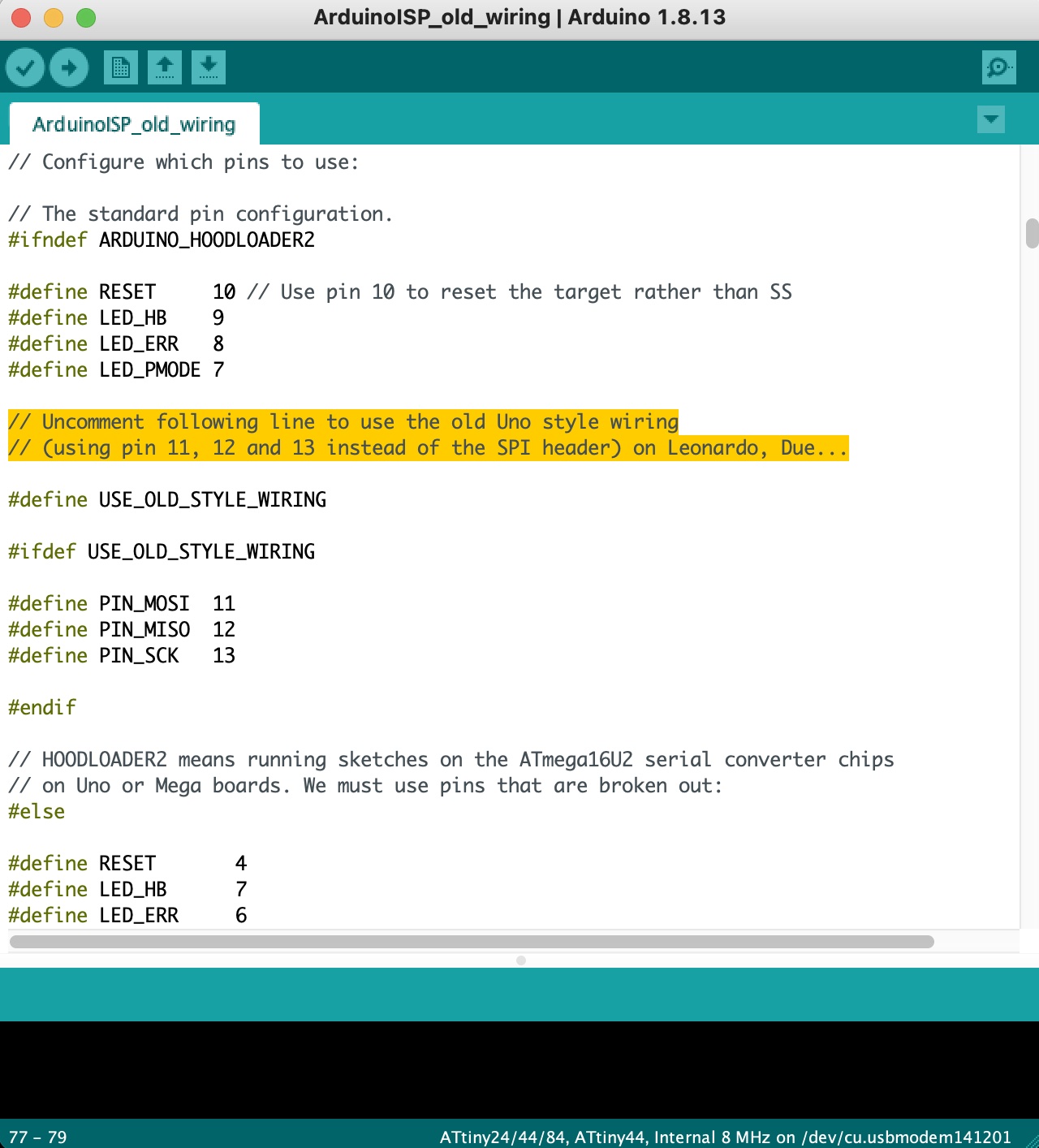
Connect the Arduino used as the programmer to a PC via USB. Upload the example sketch ArduinoISP to the board. Noted that because I’m using a Uno, I uncommented these lines to use old Uno wiring as indicated in the sketch and made a copy of the sketch.
Add ATtiny support in arduino IDE
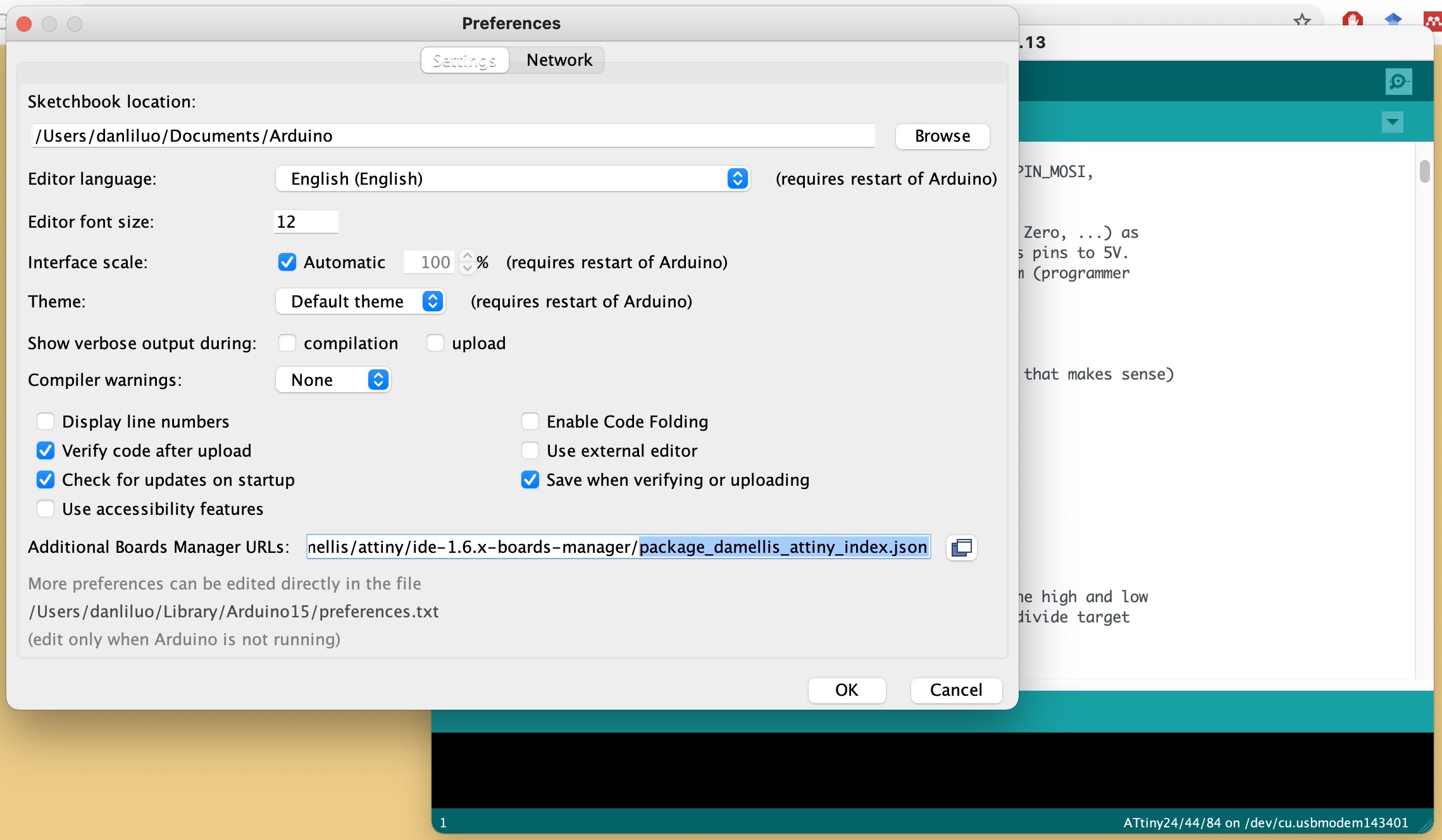
Any special boards that are not in the default Arduino board menu need to be added. In the arduino IDE, navigate to Arduino - Preference (for Mac, in Windows Preference is likely under File), enter the following URL in the Additional Board Manager URLs:
https://raw.githubusercontent.com/damellis/attiny/ide-1.6.x-boards-manager/package_damellis_attiny_index.json
Navigate to Tools - Board - Boards Manager…. The attiny boards should pop out because we just added the above link, but if not, search for attiny and install the latest version (1.0.2 at the time of this post).
Wire it up
The six AVR-ISP pins need to be connected to the Arduino board. There are many schematics online to help with that, but I find that the ArduinoISP sketch mentions very clearly which pins to connect on the Arduino board.
#define RESET     10 // connect reset to arduino pin 10
#define PIN_MOSI	11 // connect MOSI to arduino pin 11
#define PIN_MISO	12 // conect MISO to arduino pin 12
#define PIN_SCK		13 //connect SCK to arduino pin 13
And GND to a ground pin, VCC to the 5V pin. A capacitor of 10 uF is placed between GND and RESET on the Arduino board to prevent reset on the Arduino.
Use Arduino as ISP
Navigate to Tools in the Arduino IDE. Choose:
Board - “ATtiny24/44/84”
Processor - “ATtiny44”
Clock - “Internal 8 MHz”
Programmer - “Arduino as ISP”
Let’s try some blink sketch!
Flash the board
I find myself more confortable with the Arduino IDE for writing program for my board. Also, I can call on libraries in Arduino IDE which makes my life easier. I referenced to this and this for the capacitive touch sensing function. The sketch is attached here.
Demosssss!
There are three modes of touch sensing derived from the design of the board.
1 - Direct touch on the leg of the 1M Ohms resistor would activate the touch sensing.
2 - The signal pin can be wired to an external conductive surface, such as aluminium foil or copper foil, to dissipate charges. Luckily, I milled a tiny version of the ghost board last week, and now it can be the side kick of the mother ghost board.
3 - Lastly, this board is compatible with the little sweater I made in week 3. For some reason, this sweater can sense proximity when a hand approaches its surface.